The MGA With An Attitude
FUEL VENT-OVERFLOW PIPES Installation - CB-109
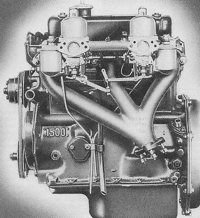
This nice picture is from some early factory publication. For simplicity of illustration several important parts have been omitted. Not shown here are the fuel inlet hoses, heat shield, throttle and choke cables with bracket, air cleaners, vent hose from valve cover to front air cleaner, and the engine mount bracket. The missing parts make this illustration a bit misleading about the ease or difficulty of installing the fuel vent-overflow pipes. Notice the picture shows the front tube installed outboard of the front exhaust runner, and the rear tube inboard of the center exhaust runner and inboard of the crankcase vent draft tube. The fuel vent pipe to block attachment "P" clip is outboard of the draft tube bracket.
This arrangement might not be too difficult to accomplish if you had the engine in open space as shown and with all manifold and carburetor parts installed. But it can be very tough to "thread the needle" for the rear vent pipe in particular when the engine is in the car. It is also effectively impossible to find access to the "P" clip on the engine block in the car with the heat shield in place. It is much easier to R&R the engine for servicing with the manifolds removed. If you attempt to R&R the engine with the fuel vent pipes and draft tube attached there is a high probability of damaging the bottom ends of the tubes by hitting the engine mount pedestal. For these reasons I have a few alternate suggestions for routing these fuel vent pipes.
My first suggestion is to run both of the vent pipes directly inboard from the float covers, across or around the fuel inlet fittings, over the top of the heat shield, and then turn downward near the ends of the inlet manifold. From there the rear pipe would run similar as shown in the picture above, while the front pipe would run inboard of the front runner of the exhaust manifold. This positions the vent pipes nicely out of the way for adjusting fuel mixture and choke linkage. A disadvantage is when dismounting the carburetors for servicing (hopefully infrequent) you would either have to disconnect the vent pipes from the float covers (which is a bit of a fiddle leaving the float covers loose) or pull the heat shield along with the carburetors which presents a gasket positioning problem and the impossible access to the "P" clip on the block.
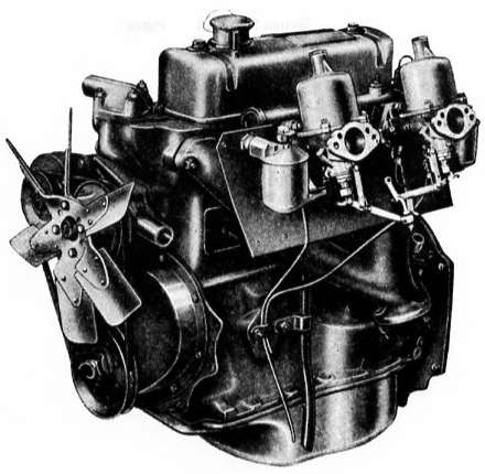
The picture above is taken from the factory Workshop Manual and would probably be proper for concours show. This picture also omits the fuel input hoses, throttle and choke control cables and bracket, and the engine mount bracket, but it does show the heat shield.
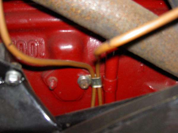
My second suggestion is similar to the picture above. Run both vent pipes downward just inboard of the float chambers, keeping the pipes very close to the outer face of the heat shield. Angle both pipes to form a "V", coming together near the bottom edge of the heat shield outboard of their attachment point on the engine block. From there run both pipes together in an "S" bend to the P-clip on the block. Keeping the pipes close to the heat shield should minimize interference for carburetor adjustments or wrenching on the bottom carburetor mounting bolts. But you still need to disconnect the pipes from the float covers to remove the carburetors because of the impossible access to the "P" clip with heat shield in place.
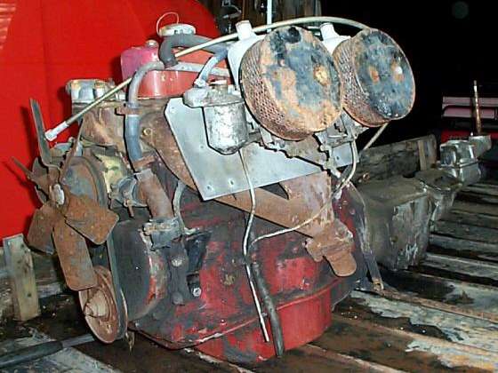
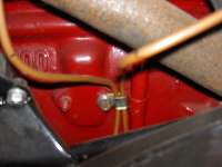
The next picture shows an engine and gearbox assembly pulled from a parts car with all accessories still attached. For a variety of reasons this one appears to be very original, possibly never before having been removed from the car since it left the factory. Note similarity to the picture above, except the P-clip is attached to the same stud as the draft pipe. To remove this from the car with the draft pipe still attached would require removing the tunnel and the lower bulkhead panel just above the tunnel (because the engine mount pedestal on frame is an obstruction). Keep in mind that the factory originally installed the power unit in the chassis before the tunnel and body were installed.
 For any of these installations of the fuel vent pipes it is best to do the original pipe forming and fitting with the engine in open space (and carburetors mounted of course). It will be somewhat more difficult to do so with the engine in the car. Once the pipes are properly formed the in-car installation is much easier. But still keep in mind the difficulty of access to the "P" clip. For this reason the vent pipes need to be attached to the engine before the heat shield is installed. I hope you will never forget that small point, or you will have another nifty lesson from the School Of Hard Knocks when you have to R&R the carburetors again or badly bruise your knuckles.
My third suggestion is likely to be much more popular for the majority of daily driver types. Since I drive a lot and subsequently have the carburetors or engine out for servicing occasionally, I lean strongly toward ease of servicing. For this approach I like to run the vent pipes downward near the sides of the float chambers, then outboard at an angle to run downward between the frame and inner fender. Unfortunately this would leave the pipes unsupported with a condition of the engine shaking during normal operation, which would lead rattling of the pipes against frame and body and to short term fatigue and fracture of the pipes. My fix for that is to cut the pipes short about at the bottom of the float chambers and continue from there with 3/16 inch bore rubber hoses to drop between the frame and inner fender. It isn't concours, but it sure is slick and easy and effective.
One last note here. However you chose to do this, do not ever terminate the fuel vent pipes above the level of the exhaust pipe. That should be intuitively obvious, but there are many MGA owners who do exactly that. You can imagine the results if a float valve should hang open and pour fuel on the hot exhaust system. Please be careful with this setup.
|