The MGA With An Attitude
INTAKE-EXHAUST HEAT SHIELD - CB-202 - page 1 of 2
This is an idea that seems to have considerable merit for a cheap fix. It is a heat shield to keep radiant energy of the exhaust manifold away from the intake manifold to help prevent vapor lock condition in the carburetors. This was submitted by Gregory Brown, and he assures me that it stopped vapor lock completely in his MGA. I haven't tried this myself (yet), so I will reserve personal judgement until I can give it a try.
If you ever get stuck in stop and stop traffic in hot weather, you may notice after a while the engine can start to stumble and sputter, may backfire with throttle, and may have very poor torque. The same thing can happen when you restart the engine after a short shut down period after a hot run. Pulling the choke full out may enrich the mixture enough to keep it running until you find another minute or two of quicker travel for better cooling. This is vapor lock condition, caused by boiling of fuel in the body of the carburetor around the main fuel jet. The factory original heat shield between the carburetors and the manifolds may do a reasonable job of shielding the carburetors from radiant energy of the exhaust manifold. But it still leaves direct exposure between the exhaust manifold and the intake manifold, which are in very close proximity. This piece is designed to block that area to reduce temperature of the intake manifold.
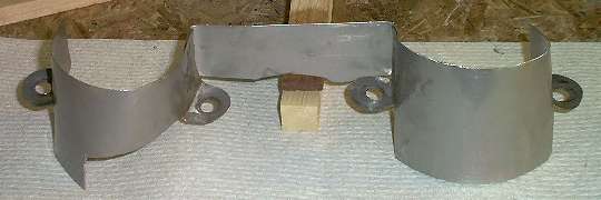
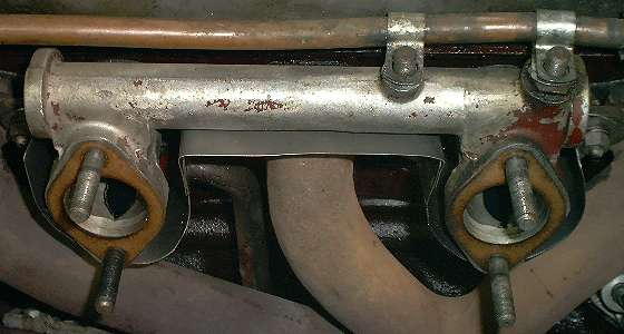
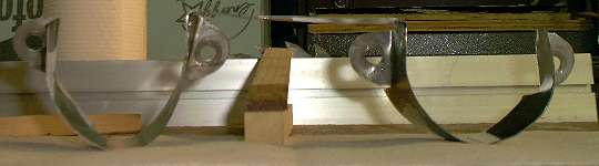
The finished part is shown here, formed from stainless steel sheet and installed on the engine. Aluminum sheet may work as well and would be easier to form, but may be more susceptible to stress cracking from vibration. This part will get very hot, so paint is not recommended.
Next below is a (rough) cutting template. This will need to be refined, but it is a good starting point. You can right click and save the image. Using 8-1/2 inch wide paper, set printer margins to 1/4 inch and print the image to fit the paper size. This should make the full image 8 inches wide, and the black area 7 inches wide. You will need to cut two pieces like this. The dash lines are approximately located to bend the mounting ears downward, then bend the part to a "U" shape. The white area needs to be cut out for the front piece only to clear the draft tube on the front tappet cover. You will also need to cut a bridging piece about 1-1/2 x 4-1/2 inches, plus small tabs at the ends which may be bent down and spot welded in place. Or with a little tinkering you could make this from a single piece about 18-1/2 inches long.
Go to next page for CAD drawings of the full flat layout and the formed part.
|