The MGA With An Attitude
A COMEDY OF ERRORS - Do Not Do This - CF-110
This picture is a good example of a number of bodges, or what not to do to your MGA. I don't usually post full screen pictures, but this was too good to pass. Click for larger image (142KB) in a separate window.
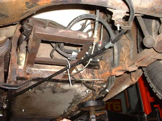
Underside of car around the battery carrier area
Let's start with the battery. Someone has installed a single 12 volt battery which will not fit in the original battery carrier, so it was placed in the boot (in the "trunk" to us yanks). The battery is not shown here, but in the boot it is not secured and is free to fall over and spill acid or short the power terminals with the first good bump in the road.
Routing of the main battery cable is also a disaster waiting to happen. Starting with it's normal position inboard of the side frame and below the floor it angles across under the floor and then up over the original battery carrier. Here it is attached with a nylon tie wrap (along with the hand brake cable) and is lying across the top edge of the battery carrier tray where the cable insulation may be abraded during operational vibration. The cable then turns back and to the left side of the tray where the original helmet connector is bolted to an eye lug for an extension cable. This connection is wrapped with a few layers of vinyl electrical tape, casually peeling loose, and is also lying on top of the metal frame where it is subject to abrasion. From there the extension cable runs upward to more problems.
Not in the picture, the back edge of the cover was cut to bend up a tab large enough to open a passage for the cable, where the cable is left to abrade against the sharp edges of the sheet metal. Above that the spare tire cover in the passenger compartment was cut to run the cable through the bulkhead into the boot. At that point the cable is pinched under the spare tire where it is abraded whenever the spare tire is moved. That could be worse I suppose. I have seen cases where a rough hole was punched through the bulkhead for passage of the cable, and the cable was left to abrade on the ragged edges of the punched hole. Leaving the battery loose in the boot causes motion of the cable to further aggravate the abrasion problem. When any point of the cable insulation wears through (and it will eventually) the resulting short circuit to body or frame will conduct a high current similar to an electric arc welder which has potential to melt steel, burn PVC insulation, start a fire in the carpet, and possibly cause explosion of the battery.
Look at the steel brake line. Under the frame just ahead of the leaf spring is a threaded junction connector. This is not a good idea, but it can be functional if done well with proper flare fittings. A compression connector in the brake line would be strictly taboo. From there the brake pipe turns inward where it is loosely tie wrapped to the leaf spring and to the battery tray. Chassis vibration and motion of the spring will induce vibration in the brake pipe which will eventually cause the steel tube to crack. Loss of hydraulic fluid in a single circuit brake system means total loss of braking function.
A replacement fuel pump has been installed. The power supply wire there originally had a ring lug terminal connected to a screw post with a hex nut. Here the connector has been changed to a push on Lucar connector. This is functional until the connector incurs some corrosion which may break the circuit, which could cause loss of function of the fuel pump. I would much prefer to retain the original screw post terminal, especially in this location where the connector is subject to road splash from the rear tire.
Look at the routing of the fuel lines. At top center of the picture the original steel pipe from the fuel tank has been cut and a hose is connected with a screw clamp. Screw clamps on hoses are okay as long as the rubber hose is in good condition. From there the hose is routed to the left where it loops around and is lying loosely against the frame tubular cross member. This provides a wear point, but at least it's a large smooth surface where abrasion might be minimal. From there the hose runs down and to the right where it connects to the fuel pump. Just before the end connection the hose runs across the top edge of the battery tray where it has been casually wrapped with duct tape in a very minimal attempt to prevent abrasion of the hose.
Another hose has been used for fuel pump output. From the pump this hose turns upward to loop over the pump and downward outboard of the leaf spring. A screw clamp connection to the original (cut) steel fuel pipe is obscured by the leaf spring. Here the hose or pipe is tie wrapped to the spring. Motion of the spring will abrade the hose or pipe, and vibration of the pipe may eventually cause cracking of the steel tube. Any fracture of a steel fuel pipe of hose would cause loss of fuel and possible fire hazard. On the inlet side a fractured fuel line could allow air to enter which could defeat function of the pump. Reduced fuel flow can lead to slow running and loss of engine power. A lean running condition may result in burned valves or pistons. A fuel pump running rapidly and continuously with little or no fuel input may overhead and burn out the points or solenoid in the pump.
Just to the left of the battery carrier you can see a bolt head and a large flat washer. This is the anchor point for a seat belt. The large washer appears to have been cut on the left side to clear the steel frame and to lie flat against the plywood. Or the washer may be tucked in between the frame and the wood panel. Either way the full load of the seat belt anchor point is taken by the plywood only, which is a rather weak way to mount a safety belt. All seat belt anchor points should be attached to the steel frame. It would be much better if the bolt was located low in the corner where the large steel washer could overlap the steel frame on two sides.
At bottom left of the picture you can see four bolts which secure the seat slide rails to the to floor. At least one of these bolts has a medium size flat washer so spread the load a bit. Larger washers would be better. The plywood appears to be water stained and possibly delaminating at the rear edge, so the seat attachment my be even less secure than it appears. The seat rails with one hole at each end for a single bolt are replacement type parts from the MGB model car where the bolts are screwed into weld nuts in the steel floor pan. When using these rails in the MGA you need to use large flat washers under the floor to distribute the load over a large area of the plywood.
Original MGA, at least early production cars, used a multiplicity of wood screws to secure the seat slide rails to the plywood floor. My car (built in August 1957) has provision for three wood screws at each end of each rail, for a total of twelve screws for one seat. For replacement parts (and possibly some late production MGA) where the single bolt rails are used, the plywood floor panels are sometimes fitted with flange nuts, commonly called "T" nuts. These have a flange about the size of a standard flat washer, which in my opinion is only minimally adequate when the plywood is new and in very good condition. These are prone to working loose and pulling through with the slightest deterioration of the plywood. If the seat rails are installed over the carpet they will be more prone to wiggle around and work the bolts loose.
At bottom center of the picture you can see a round lifting pad which is part of the maintenance hoist used to lift car. It is commonly prescribed to position such lifting points under the side frame rails of the MGA. Before you do that you should check very closely to be sure that all fluid lines and electrical cables are routed under the floor inboard of the frame where they belong. Routing any of the pipes of cables under the side frame rail is courting disaster.
|
