The MGA With An Attitude
ALTERNATOR INSTALLATION, Any Style - AC-201
After 355,000 miles running with a generator in my MGA, it was time for a change. I have not had many problems with a generator (19 or 22 amps), and it is (usually) a perfectly adequate electrical power source for a stock MGA. But I finally got fed up with the poor quality of modern replacement Lucas "style" control boxes that drift out of adjustment over time and tend to fail without notice in rather dramatic fashion. It would be bad enough for a control box to fail prematurely, and I could almost live with periodic replacement. But the control box will often fail with the regulator contacts in the closed position, which causes the generator to overcharge and suffer internal meltdown. Then I get really ticked off with having to replace what was otherwise a perfectly good generator along with the control box. One such incident too many finally swayed my judgment to go non-standard in the interest of long term economics (and hopefully fewer failures on the road).
Since this it not a matter of needing more electrical power, a low output alternator would be perfectly adequate, and maybe the smaller the better. Also a small price tag would be nice (since I'm so tight I squeak when I walk). I like the tiny little alternators made special for race cars, but sticker shock put that idea away pretty quick. The Lucas alternator used for the late model MGB is 42 amps, fairly small diameter, and can be bought as a bolt-in kit, which is a great advantage. Then again, the Lucas alternator is known to have some reliability issues, and the kit price is a bit much for a handy fellow looking to get by on the cheap. Some people prefer a Bosch alternator while some recommend AC Delco for a low price unit (at least in North America). Truth is, if you can physically mount an alternator on the engine, almost any alternator will work. The rest of this article will serve as an example of some of the odd issues you may deal with if you install any alternator that was not specifically designed to fit the MG.
Early production alternators from the 1960's commonly used an external regulator, similar to a generator. Some even had selenium rectifiers. With the advent of higher power diodes the alternator took a big jump in evolution with the diode bridge rectifier. By the early 1970's many alternators were using internal transistorized regulators, making them easier to install (and more reliable). By about 1990 many cars were switching from multiple V-belts to serpentine flat belts for accessory drive. The easy solution then for an alternator for the MG would be one that is internally regulated and having a V-belt pulley.
 To get an idea of the variety of what might be available I checked eBay for "alternator", and was promptly presented with over 2500 items for consideration. There is certainly no shortage of good used alternators on the market, many selling for such ridiculously low price that you may consider shipping cost as a prime motivator. After some browsing on eBay one item suddenly reminded me that I had a spare alternator from a 2nd generation Mazda RX7 stashed away in the garage for several years (a parts-car left-over), and it was likely never going to be used. So I fetched it down for a casual look. It appears to be more than a little overkill at 70 amps, but the price was certainly right, and no waiting for delivery. Mitsubishi alternator, anyone?
First order of business was to remove the generator from my MGA and hold the alternator in place to be sure there was enough space available to accommodate it. There was. It is short front to back but larger in diameter than the generator, so it has to sit well above the engine mount and not hit the inner fender. No problem there.
 I also had a couple of jumps on the job, having a spare engine on an engine stand, and also having in hand one of the extended rear brackets from a 1275 MG Midget with alternator.
I bolted the extended rear bracket to the engine block and slipped a 5/16 inch steel rod through the holes to check alignment. The rear bracket needed a little adjustment (with big vice and heavy hammer) to square it up, but it was soon in place with the alternator hanging on the rod. The Mitsubishi alternator is even shorter than
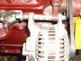 the Lucas alternator, so there would be a little space to make up in back. The more pressing issue was that the belt pulley was 1/8 inch too far forward. Fifteen minutes at the bench grinder with a dial caliper in hand took care of that problem as I removed 1/8 inch of material from the back of the front mounting ear on the alternator (click on picture for larger image in separate window).
The alternator has a steel bushing in the rear mounting ear that can move fore and aft up to 1/16" total (with a little encouragement). In original installation this is intended to allow the unit to mount with the two ears straddling a fixed width pedestal, and the bushing moves a bit to accommodate manufacturing tolerances. This makes it easy for me to rig up some spacers. For the prototype setup I used a hand full of 3/8" hex nuts which slip right over the 5/16" rod. As fate would have it, 3 nuts = 1 inch, and the center space was very close to 2", so half a dozen hex nuts did the trick. Two more hex nuts behind nicely made up the space to the rear bracket. The rear bracket also has slightly slotted mounting holes (see larger picture with loose bolts) so the bracket can float a bit and the two hex nuts are close enough.
As a matter of expediency I cut the rod to length and threaded both ends 5/16-24 UNF. The back end got two hex nuts jammed together to make a bolt head, which was quicker than welding one nut in place. The front end got a steel flat washer to protect the aluminum ear on the alternator, plus a lock washer and hex nut. Original bolt for this alternator was 10mm, so the mounting holes are a bit larger than the 5/16" rod. Just push the unit gently toward the engine block to square it up while tightening the long bolt, and it makes a very rigid attachment. I will consider later if I might replace the long rod with two shorter bolts to eliminate fiddling with the half dozen hex nuts in the middle, or maybe make a tube spacer or two for neatness.
With the alternator held temporarily in place I ran a tape measure around the pulleys to determine required belt length. I will not post the belt size here, as various alternator installations may need different belt length. I then took a quick trip to the auto parts store for the belt and a bracket. I wanted a "J" bracket to put the adjustment point on the outside end for easier access. I found what I needed at local store, one of those chrome dress up parts for about $12, which was the biggest expense of the whole project. The alternator bracket is a Spectre 4226 from AutoZone.
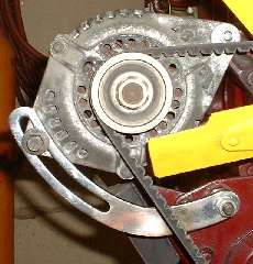 As received the "J" bracket was about 14 inches long with two holes near the straight end. I held it in place long enough to eyeball the needed length and promptly cut off part of the long straight end (leaving a little extra length). I then removed the adjusting link Pillar from the engine front plate, substituted two LARGE hex nuts in its place for a spacer, and put it together temporarily with a C-clamp. This allowed for alignment of the long curved slot to be concentric to the top pivot point so the alternator could swing for belt adjustment without moving the J-bracket. (Also the front face of this alternator has a dome shape, so if the adjuster bracket crossed at an angle it would not lie flat). Unfortunately the bottom end of the J-bracket then ended up about an inch lower than the original location of the Pillar bolt. Bummer.
I could have drilled a new hole in the engine front plate while the engine was on the stand, but that would be nearly impossible as a retrofit with the engine in the car without removing the radiator. A more reasonable fix was easy enough. I clamped the blank end of the J-bracket flat side up in a vice, then used the acetylene torch to heat the outside of the bend cherry red for 2/3 width of the bracket and 1-1/2" length. Then I bumped it on the outside of the bend near the base of the slot with a heavy hammer to bend the bracket the hard way to a tighter radius for a short distance, stretching the metal in the heated area to increase the outside circumference. Follow that with a pinch in the vice to be sure it went flat as it cooled.
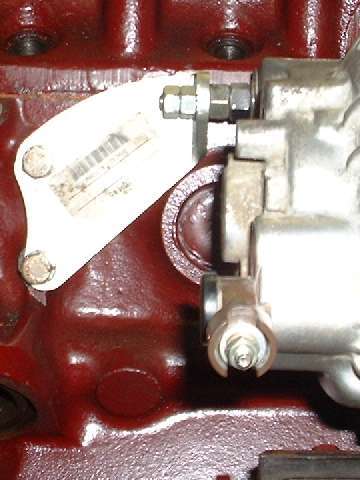
After cooling I set the J-bracket up with the C-clamp again, this time passing directly over the hole for the Pillar bolt. Then I drilled the hole in the J- bracket for the Pillar bolt, cut the base end to final length, and ground a radius on the end to be neat. The J-bracket is 8-1/2" overall length (the short way) with the new hole 1/2" from the end. Follow that with a good buffing using a Scotch-Brite wheel, and you see the result in the picture. The bracket later got a touch of primer and Chrome paint to prevent rusting where I damaged the plating.
The adjusting bolt that is screwed into the lower ear on the alternator has an 8mm thread and 12mm hex head. I am sorely tempted to drill out the hole in the alternator and install a 5/16-24 HeliCoil and matching bolt so I don't have to carry a 12mm wrench in the traveling tool kit.
A quick reminder here that the vehicle electrical system needs to be converted from positive to negative ground.
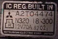
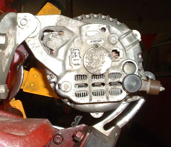
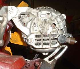 Now we have a rear view showing the wiring terminals, which is a bit different than the Lucas alternator. Just left of center there are two spade terminals. There is a small diagram on the model number tag shown near top of this article. The vertical spade terminal "L" will take the connection for the MG ignition warning light (or a relay coil as used in the RX7). This terminal sinks current with ignition on and engine not running, but rises to system voltage when the alternator is working (extinguishing the warning light or dropping out a relay). The horizontal spade terminal "R" needs a 12 volt feed from the ignition switch to power the internal regulator. This I will connect with a small (White) wire from the supply side of the ignition coil. However, it is well advised to put the White coil supply wire and the White alternator "R" wire together in a single connector at the coil. This way the Regulator power wire cannot be disconnected from system power while the engine is running, which could damage the alternator (see notes at bottom of page). With this separate power feed a burned out ignition warning lamp will not disable the alternator as it does with the Lucas alternator.
The brown insulated terminal "B" at lower right is the direct battery connection. This terminal will always have battery power, even when the car is parked with engine off. Since this alternator is capable of producing up to 70 amps (given enough load), It will need a larger wire than exists in the original MG wiring harness. I will leave the original fat Brown wire in place for connection to the body power feed (and to the main battery cable). I will install an additional 12 AWG Brown wire for direct connection to the main battery cable at the MGA starter switch (or solenoid or starter for the MGB).
With this setup the new large wire can take the increased alternator output directly to the battery cable. The original brown wire running from the battery cable to the (original) control box connection point does not need to be larger because it only conducts the same current as original for the vehicle electrical load, or feeds back only part of the charging current from the alternator to the battery. Same applies for the original wire from the generator (alternator now) to the original control box contact point, only conducting part of the alternator output. The two fat brown wires running in parallel can now combine their load carrying capacity to take the full output of the alternator. This may come into play if it is called upon to recharge a badly discharged battery, or if it is used to jump start another vehicle.
Mitsubishi alternator electrical diagram

Caution
a) Be sure the battery connections are not reversed, because this will damage the rectifier.
b) Do not use high-voltage testers, such as a megger, because they will damage the rectifier.
c) Remember that voltage is always present at the alternator (B) terminal.
d) Do not ground the (L) terminal while the engine is running.
e) Do not start the engine while the coupler is disconnected from the (L) and (R) terminals.
My RX7 Workshop Manual has more than a dozen pages of maintenance information for this alternator, which I will NOT repeat here. Different alternators may need slightly different electrical hookups and different maintenance information. Whatever alternator you may chose to use, it will be your responsibility to procure the proper information for that alternator, and keep this information with your vehicle "modification" documentation.
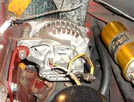 
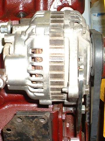
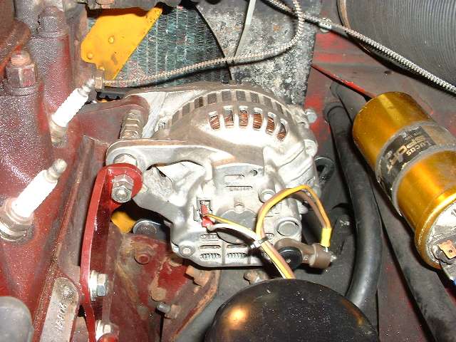
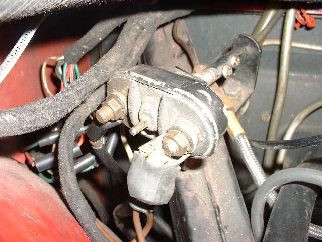
Here it is installed in my MGA. Photo at left shows the wires at back of alternator. The small Yellow/Green wire is the original Field wire, now connected to the ignition warning lamp (at original control box point). The small white wire is the new ignition feed (from the ignition coil power input point). The larger Yellow wire (14 AWG) at right is the original Dynamo wire, now connected to the Battery wire (at original control box point). The large Brown wire is the new 12 AWG wire connecting directly to the main battery cable (at starter switch). The fat Yellow and Brown wires share a single end connector. Watch out for the live battery terminal here. I intend to cover this with a rubber boot. If I can find the right 2-pin connector plug I will install that for the smaller wires to avoid the possibility of switching those connections. This boot and connector are standard parts from any car equipped with this alternator.
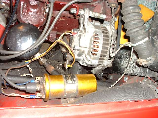
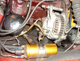
In photo at right above you can see where the new White wire is connected to the ignition supply wire at the ignition coil. Notice that I put both white wires into a single connector to make it impossible to disconnect the alternator's Regulator power feed (at least at this point) while the engine is running. In both photos above you can see that the new J-bracket comes fairly close to one of the oil cooler hoses. I adjusted the hose connector at the oil filter to move this hose closer to the inner fender. If this should ever become an interference problem I would install a bracket to secure the hose against the inner fender.
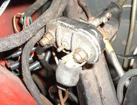 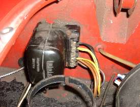
Photo at left here shows the battery cable connections on the starter switch. I have relocated the starter cable to the terminal closer to the inner fender. The main battery cable is now on the terminal post closer to the engine (easier to reach for jumper cable or battery charger). On the same terminal post with the battery cable are the original brown wire going to the control box point, the new heavy brown wire from the alternator, and a fourth wire long ago routed to a power jack in the passenger compartment (a dual cigar lighter jack). That last one is the gray wire below the starter switch. It is difficult to get the original rubber boot over the terminal post with all these wires attached.
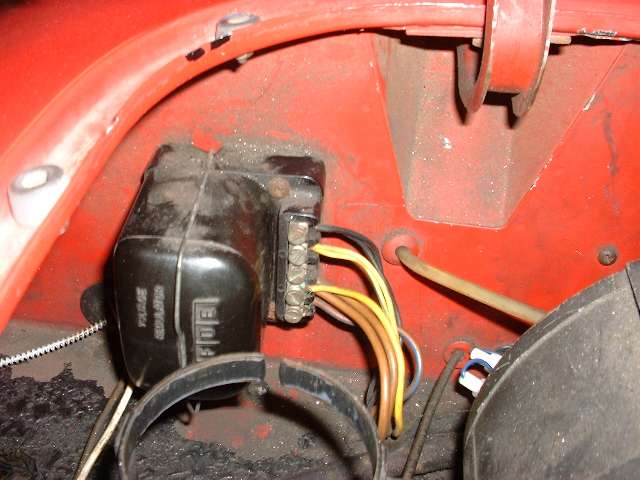
Photo at right above shows the prescribed rearrangement of wires to bypass the original control box function. The original Yellow Dynamo wire is moved to the A or A1 terminal to be connected directly to the battery (Brown wires). The original Yellow/Green Field wire is moved to the D terminal to be connected directly to the ignition warning lamp (small Yellow wire). The black wires remain connected to ground the wiper motor. These wires are all on the end of a separate harness branch. As such, you could connect the wire ends with wire nuts (soldering preferred) in three bundles, shrink wrap or tape cover the ends, and drop this harness branch behind the heater box to be neat while removing the original control box.
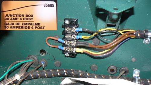
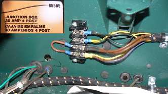 In this configuration the control box internal function is entirely bypassed, so the box could be replaced by a barrier strip. This one was installed by Jim Mail in New Hampshire, USA, picked up at Pep Boys for about $5 (and fits in the original screw holes). You could install another identical barrier strip on the back side of the bulkhead (same screws). This could accommodate added wires for a radio or other power accessories as well as off loading some power wires from the ignition switch.
With the ignition power feed to energize the alternator field coils (in the armature), and the high current capability, this alternator turns out 14.52 volts at 800 rpm engine slow idle speed with all lights and accessories switched on. With all lights and accessories off it can be revved up to any speed and never exceed 14.58 volts. So the internal regulator can give 14.5 +/- 0.03 volts under all running conditions, very stable indeed.
Now I wonder what I can use the extra 50 amps of power for? I could install 4 x 100 watts off road driving lights, and a 400 watt stereo. That could scare the bejesus out of some jack rabbits and rattle snakes in Baja, Mexico. I have no idea what people may be thinking when they mention installing a 110 amp Saturn alternator in an MG. I'm sure I would be happy with 42 amps from the small Lucas alternator (if I wasn't so cheap).
Addendum:
Three months later I had the radiator out (for an unrelated reason). With a little extra time available I finally drilled that new hole in the engine front plate exactly one inch below the original hole to relocate the adjuster bracket pedestal. I then bought another J-bracket, cut off and drilled without making the heat bend, leaving it as a simple radius bracket (now all chrome, no paint). I also made a pair of tube spacers to replace the eight large hex nuts on the main pivot mounting bolt.
Since the nut on the pedestal is hard to reach with the (aftermarket) radiator shroud in place, I removed the lock washer and hex nut, replacing them with a flat washer and Nyloc self-locking nut. Now I can tighten the pedestal nut before installing the alternator, leaving it just loose enough to allow some forced rotation of the bracket to align with the alternator at final assembly. The alternator can then be installed and may be moved for belt tightening without needing touch the lower bracket bolt.
|
 Now we have a rear view showing the wiring terminals, which is a bit different than the Lucas alternator. Just left of center there are two spade terminals. There is a small diagram on the model number tag shown near top of this article. The vertical spade terminal "L" will take the connection for the MG ignition warning light (or a relay coil as used in the RX7). This terminal sinks current with ignition on and engine not running, but rises to system voltage when the alternator is working (extinguishing the warning light or dropping out a relay). The horizontal spade terminal "R" needs a 12 volt feed from the ignition switch to power the internal regulator. This I will connect with a small (White) wire from the supply side of the ignition coil. However, it is well advised to put the White coil supply wire and the White alternator "R" wire together in a single connector at the coil. This way the Regulator power wire cannot be disconnected from system power while the engine is running, which could damage the alternator (see notes at bottom of page). With this separate power feed a burned out ignition warning lamp will not disable the alternator as it does with the Lucas alternator.