The MGA With An Attitude
SIMPLIFIED WIRING DIAGRAMS - ET-101C
SIMPLE STARTER
Shown below is the MGA starter circuit diagram. They don't get much simpler than this. The starter is not polarity sensitive, so if you reverse the battery, it can be negative earth just as well as positive earth.
At 08:00 AM 4/16/2009 -0600, David Lentinello wrote:
"What is the order to the wiring for the starter switch and starter. Does the battery cable bolt on to the starter switch to the left, right or center??? Brown .... black cable ...."
There are only two terminals on the starter switch. It is a simple continuity switch, so the terminals are interchangeable. The brown wire connects to the terminal holding the battery cable.
For cleanest routing you might think to put the battery cable nearest the inner fender, and the starter cable on the inboard terminal (closer to the starter motor). However, it is sometimes convenient to use the front end of the main battery cable as a connecting point for a battery charger or jumper cable. It is difficult to reach (without shorting something) when located nearest the inner fender. I like to put the main battery cable on the inboard terminal where it will be more convenient to connect a jumper cable or battery charger clip. That leaves the
 starter cable alone connected to the outboard switch terminal (closest to the inner fender).
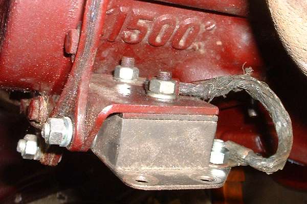
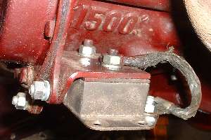
Notice that the starter has internal ground. That means the starter housing has to ground on the engine back plate, and the engine has to be grounded to the chassis. Do not forget the engine grounding strap that needs to run across the left engine mount.
|