The MGA With An Attitude
HARNESS INSTALLATION At 04:28 PM 2/8/04 -0500, Fred Stankovic wrote:
 From there the harness continues to follow the inner fender forward and downward. The bulk of the main harness terminates with several bullet connectors just inside the front corner of the main body shell. Some wires are left to run across the front on the bonnet latch support for left side lamps, while a small trunk runs below the air pan for the horn(s) and fog lamp (when installed).
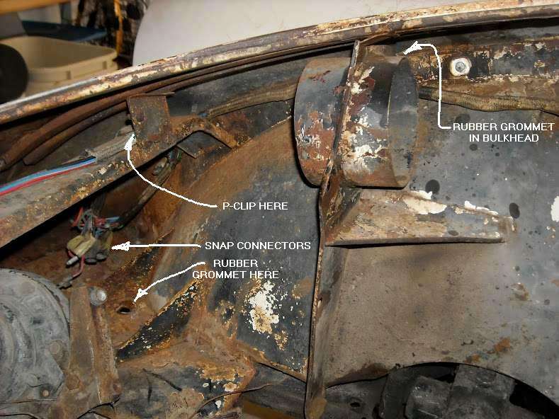
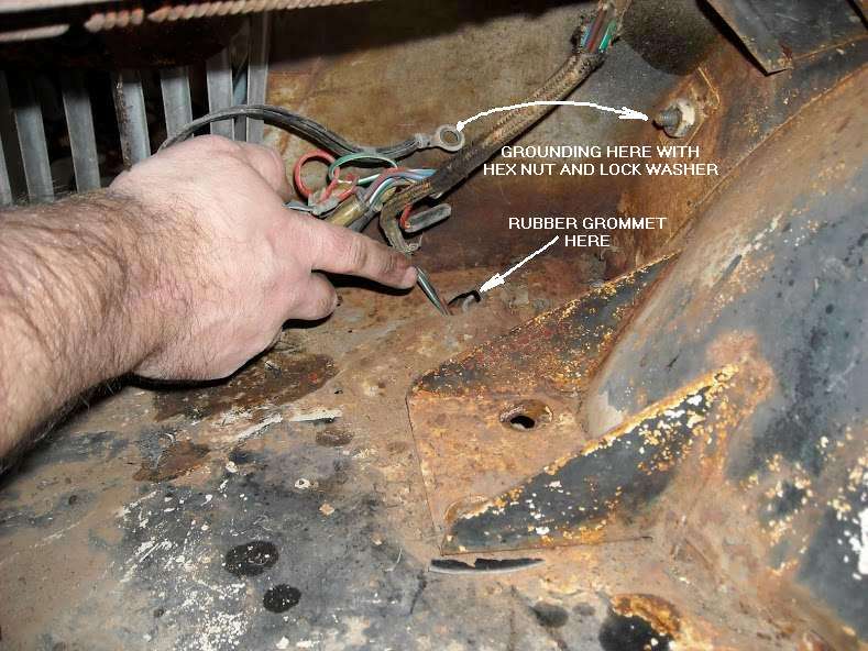
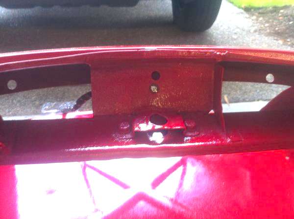
 The front harness (continuation of the main harness) runs from corner to corner across the front of the main body shell. Parking lamps, turn signals, and head lamps join to the front harness with snap connectors. In the right front corner there are 3-way connectors for high and low beam headlamps, parking lamps and ground wires. There is also a ring lug connector on the black wire circuit for grounding. This will attach to the tip end of a long body bolt with a hex nut at the second bolt position above the horizontal air pan. In case anyone would ever notice, this is why there are odd numbers of long and short bolts in the Service Parts List for attaching the wings to the body. This one grounding bolt is long where others are short. The factory did it that way because the harness was installed in the body before the body was set on the chassis, and they needed a fixed grounding point before the bolts for body to frame were installed. Lots of people connect the ground lug to a bolt where the body attaches to the front frame extension, which is serviceable but not original. 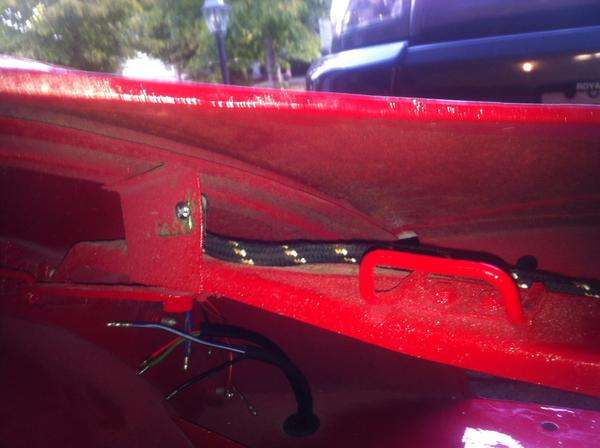
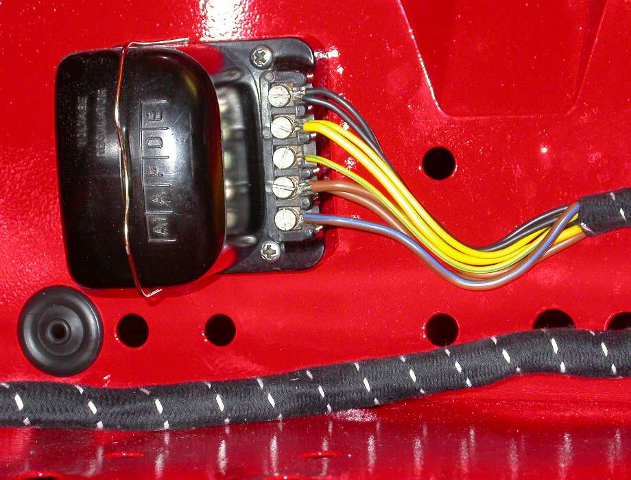
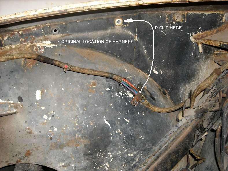
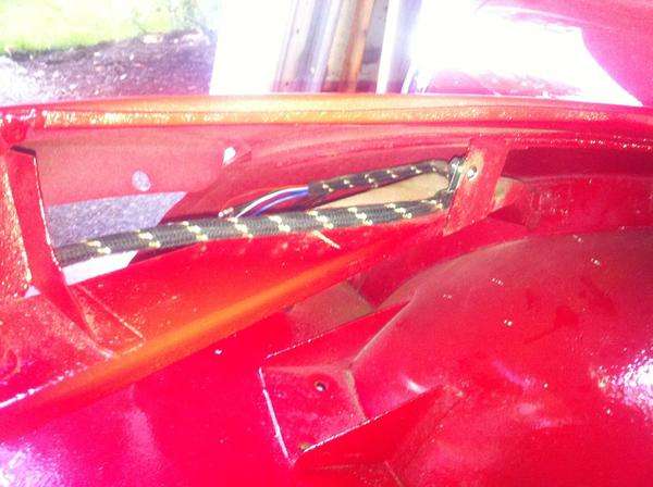 Many people will leave the front harness lying on the air pan just inside of the grill (unsightly). With a little fiddling you should raise it and attach it to the bonnet latch support brace with a few P-clips for better appearance (as original). Do not allow cable ties to interfere with the operation of the bonnet latch mechanism. With a lot more fiddling you might run the cross harness below the air pan, but that would not be original style.
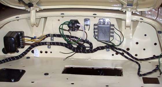
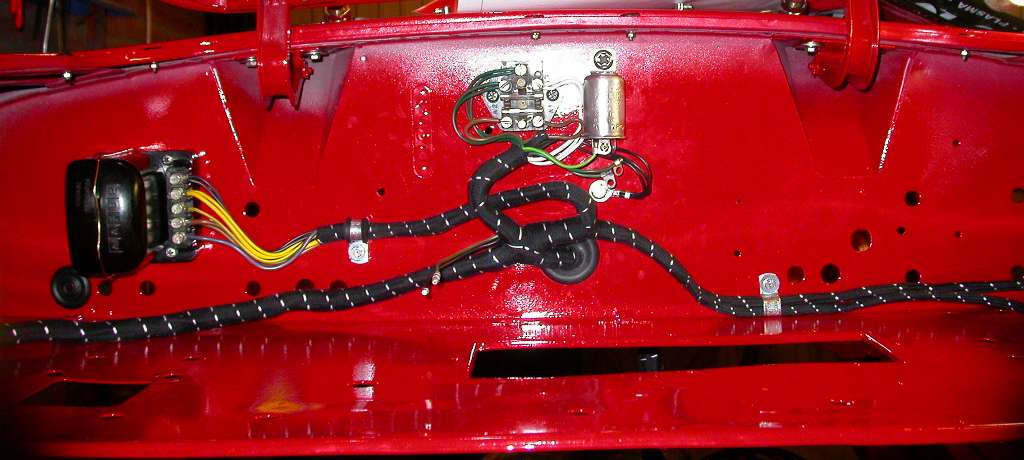
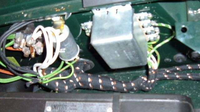
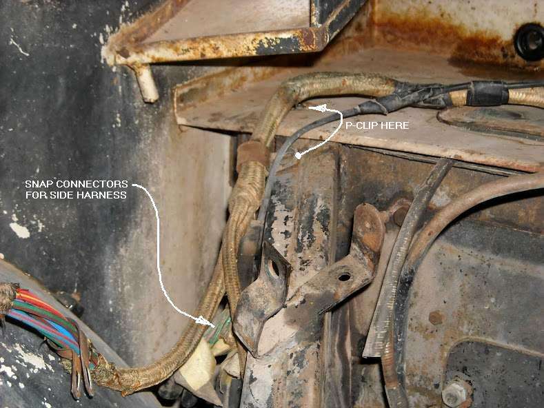
 There must be rubber grommets where wires for the corner lamps pass through the air pan You might try to route the wires to put the snap connectors inside the nose of the main body shell above the air pan for best protection from road splash. Keep in mind that this area is very difficult for service access after the radiator is installed. The 4-inch air ducts also attach to the body in this area, making access for wiring even more difficult. A much easier solution is to position the snap connectors just below the air pan for easy access from underneath or through the wheel well. Then you get to decide how to deal with road splash, and how to attach corner lamp wires for good physical support and strain relief. The dash harness section connects to the dash components and will have only a single wire (brown with black stripe) remaining to connect to the main harness with a large snap connector. The dash harness is intended to be completely connected to the dash assembly before the dash is installed in the car. Then the dash is "offered up" face down near the position of final installation while the main harness connections are made to the dash components. Once the dash is completely wired it is bolted into place. As the heater control panel and lower edge dash braces are installed, two wires for the heater blower switch (when fitted) are connected with snap connectors. There is a minor difference for the MGA Twin Cam wiring harness. In the engine bay the ignition coil is on the left side, so there is a separate small branch of the harness for those wires. Otherwise right hand drive and left hand drive cars use the same harness for same model cars. The large trunk of the main harness passes through the bulkhead near the center of the car, and there are separate small branches of the harness for the control box and dipper switch which can be re-routed for either LHD or RHD. Similarly the dash harness can be flipped over to service either LHD or RHD, and the large and small instruments may be installed in any configuration while the harness will still reach. 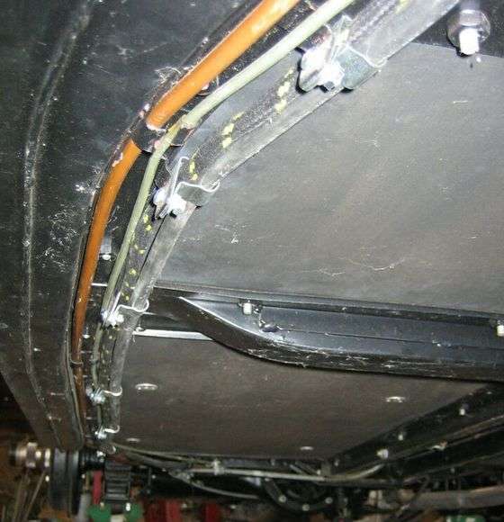 The side harness runs from the snap connectors in the engine bay downward, splitting out wires for the brake light switch, then back under the frame splitting out wires for the fuel pump, the fuel level sender unit, and a black ground wire with a ring lug which attaches to the frame near the fuel tank. The side harness ends with more bullet connectors just behind the right rear wheel. The main battery cable and the side harness run together and are attached to the inner side of the frame below the floor with "P" clips. These clips need to be mounted in upward orientation to tuck the cables in along the inner surface of the frame for good protection from road hazard. The side harness runs from the snap connectors in the engine bay downward, splitting out wires for the brake light switch, then back under the frame splitting out wires for the fuel pump, the fuel level sender unit, and a black ground wire with a ring lug which attaches to the frame near the fuel tank. The side harness ends with more bullet connectors just behind the right rear wheel. The main battery cable and the side harness run together and are attached to the inner side of the frame below the floor with "P" clips. These clips need to be mounted in upward orientation to tuck the cables in along the inner surface of the frame for good protection from road hazard. 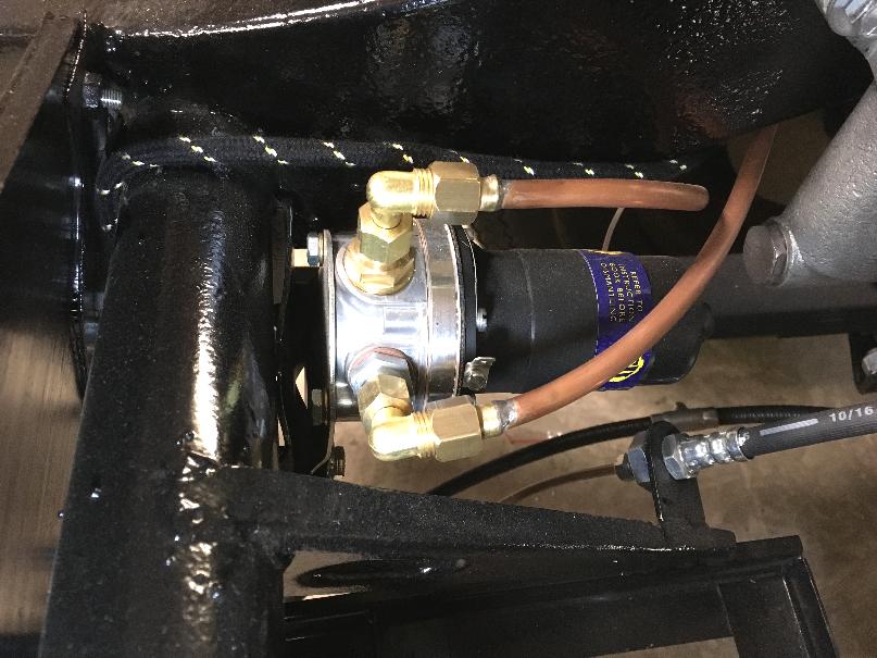 The side harness should run inboard of the front leaf spring mount, then upward aft of the rear vertical floorboard, over top of the round frame cross tube, then along with the fuel pipe. Once past the fuel pump, then run outboard under the frame and above the leaf spring, then following outboard the frame over the arch, attaching with P-clips. It is very important that the pipes or cables do not run under the frame or leaf spring mount points where the lines might be damaged by use of a frame hoist. This is why the harness does not run outboard of the frame before the leaf spring.
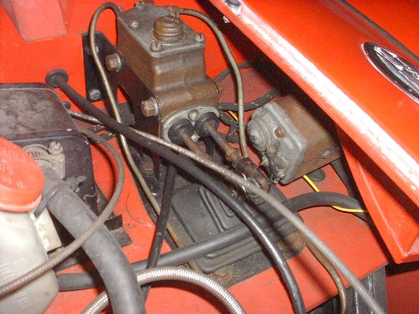
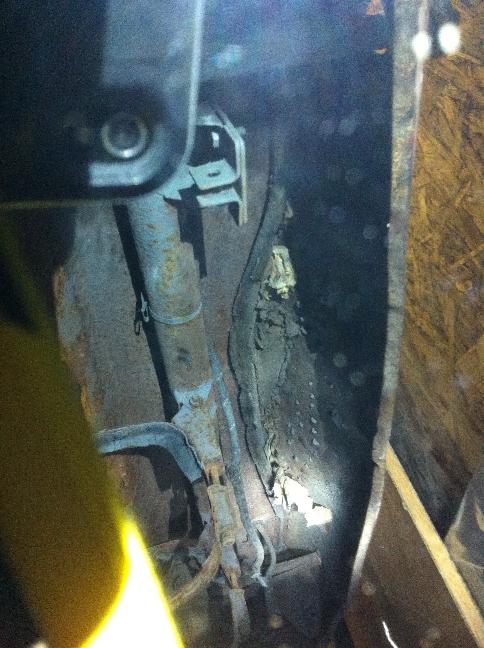
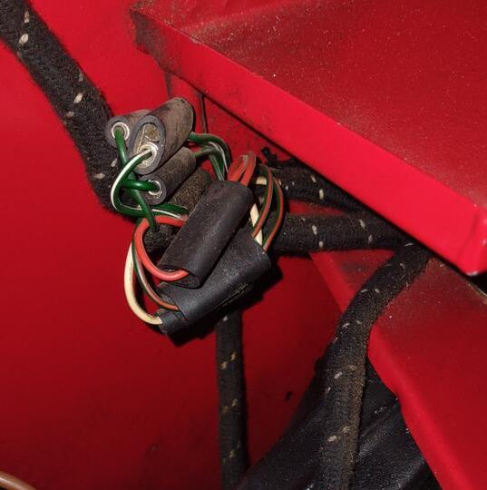
 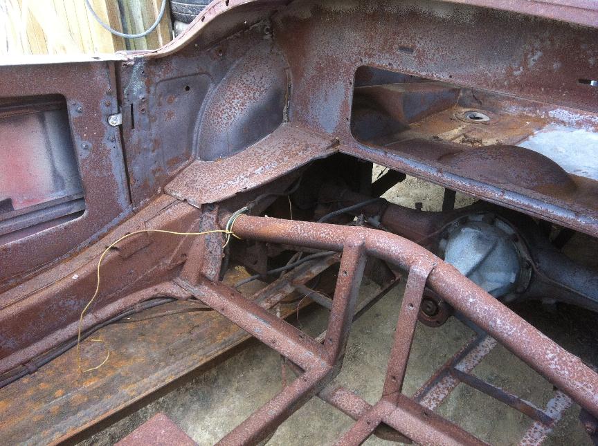 I have a personal knee jerk reaction to the harness running over the top of the round tube like that. Photo here shows an original MGA 1600 with the harness cloth jacket completely abraded away with the electrical wires rubbing directly on the round tube. If the car continued to be driven like that, it would be only a matter of time before the insulation wore through and the wires shorted to ground on the chassis. To run the harness in that location there should be a P-clip immediately below the round tube, and another P-clip immediately aft of the round tube, to serve as strain relief and keep the harness from dragging on the frame at that point. Unfortunately the factory documentation is very vague on where the P-clips are located.
 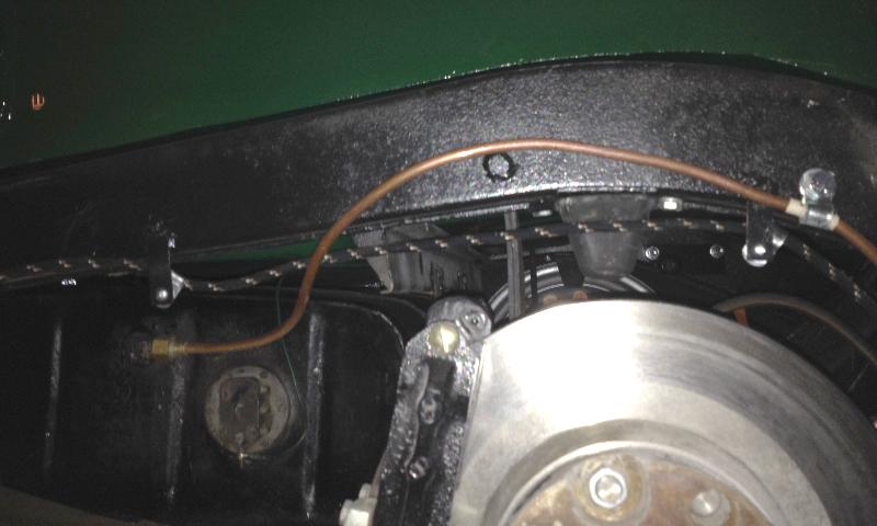 There are two hanging welded brackets on outboard side of the frame near the fuel tank. More P-clips go here to support the side harness. The rear most hanger is also the grounding point for the black wire in the side harness to provide ground for the rear harness, figuring for a 4-way snap connector between rear and side harness. This is also a convenient point to add a ground wire for the fuel tank if the steel fuel line is cut and connected with rubber hose. (Picture shows rear disc brakes of a Twin Cam chassis).
  The illustration at left comes from the MGA Twin Cam Workshop Manual, showing an additional P-clip for the harness to be attached to one of the screws securing the right side bump stop above the rear axle. Parts in these illustrations are not necessarily drawn in correct position or orientation. I suspect this clip should be placed on the rear most outboard screw, so it will be more equally spaced between the weld tabs on the frame. Purpose of this clip is to hold the harness high enough that it cannot be bashed by the rear axle or parking brake caliper or brake cable when it hits full bump height compressing the rubber bump stop. I suspect this extra P-clip may be unique to the Twin Cam and "Deluxe" cars with disc brakes on the rear.
 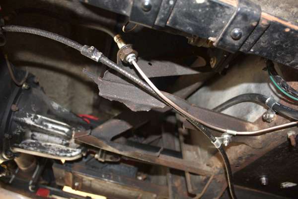 More photos:  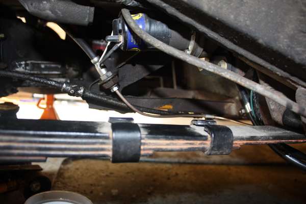 The side harness was grounded on the frame before body installation. The black wires were "plugged in" when the body was installed. You should be able to R&R the body or harness without removing a bumper bolt, which is why there is (supposed to be) a black wire in the side harness. The fuel pump originally has a separate ground wire going to an extended floorboard bolt with a hex nut. There have been some replacement wiring harnesses with a large bore end terminal on the rear harness black wire(s) intending to ground on the rear bumper bracket frame bolt. 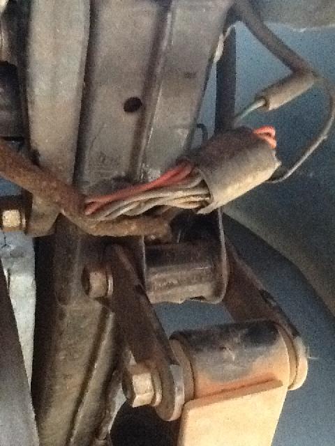 This may be functionally better, as it eliminates the 4-way snap connector for black wires between rear and side harnesses, but it is not as original. Problem there is that the rear harness was originally installed in the body before the body was installed on the chassis.
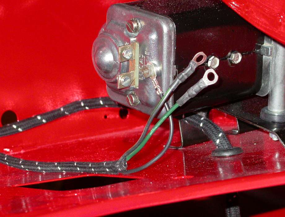
 Never run the harness through the rear spring shackle. That would be pretty much guaranteed to abrade the harness and short the wiring to ground. It is acceptable to run the harness through the fixed frame aperture above the spring shackle where nothing moves. The rear harness starts with bullet connectors aft of the RR wheel and runs across the back of the car to connect all of the rear lights. The lamp fixtures should not rely on grounding to the body. Each fixture has a black ground wire which will run to the point aft of the right rear wheel where they will join with a multi-position snap connector. The rear harness connects to the side harness with snap connectors, including splitting the tail light wires (and the brake light wires on the 1600 model). This bundle of snap connectors aft of the rear wheel is a long term problem for road splash and corrosion. There is information in another article about how to live with bullet connectors. The short of it is, stuff them with silicone grease, wrap the whole bundle in vinyl tape, and attach it to the bumper frame bracket for good support and strain relief. This wouldn't pass muster in a concours show, but it will eliminate some headaches later. Picture below left shows the harness joining snap connectors taped up and tied to the bumper support iron. It also shows the 1500 type rear wing with three holes for two bolts and the tail lamp harness run. When the lamp assembly is installed there would be flat washes, lockwashers, hex head bolts, and a rubber grommet for harness passage through the sheet metal wing. 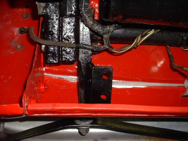

Photo at right shows the harness run with rubber grommet through the rear valance for the rear number plate lamp. The 1600 car would have one more hole higher up in the rear wing with another grommet and another harness branch with two wires for the additional turn signal lamp. British Wiring, Inc, may sell separate sections of the harness. Check here: www.britishwiring.com. They can make any reproduction or special harness on special order, keeping in inventory most of the more common ones. Original MGA harness for the earliest cars, through about 1957 used black rubber insulated wires with the color and stripes added as a cloth braid on each individual wire. The entire harness was then wrapped with black cloth braid with intermittent yellow stripes commonly referred to as bumble bee stripes (more like short yellow dashes). |