The MGA With An Attitude
TURN SIGNAL RELAY Test - ET-105A
In case you may think the prior page was a bit overwhelming, Richard Northey
in Bow, New Hampshire, USA asked:
"How can a turn signal relay be tested off the car"?
I like that. Setting the rest of the car aside, you only need a battery (or 12-volt supply), three jumper wires, and a test light. For reference, you may like to see the diagram for the MGA 1500 turn signal circuit (but it is not required for this test). Battery polarity does not matter, as the relay is not polarity sensitive.
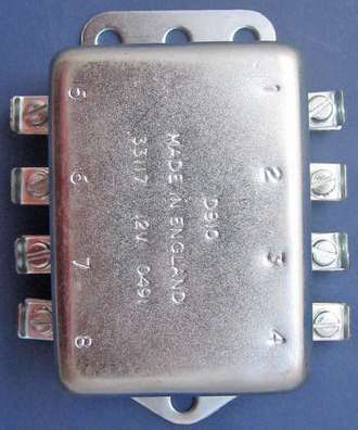
From battery run a ground wire to the base (mounting flange). From battery run power to relay #5 (brake switch input). Ground test light on the relay case. Probe terminals 3 and 7, which should have power output for the brake lights.
Disconnect power from #5. Jumper power to relay #1 (simulating power output from flasher unit to relay). Jumper power to relay #8 (simulating power output from T/S switch to relay). This should make the left turn relay click, resulting in power output on #7 and #6 (left rear and left front turn signals).
Disconnect power from #8. Jumper power to relay 4 (simulating power output from T/S switch to relay). This should make the right turn relay click, resulting in power output on #3 and #2 (right rear and right front turn signals).
|