The MGA With An Attitude
SINGLE POLE SWITCH Anatomy- ET-131
BMC part number 27H5278
On 2/5/2016, Mark Wellard in Australia wrote:
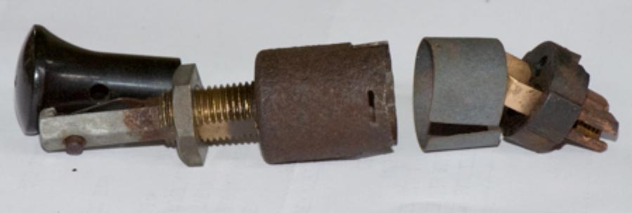
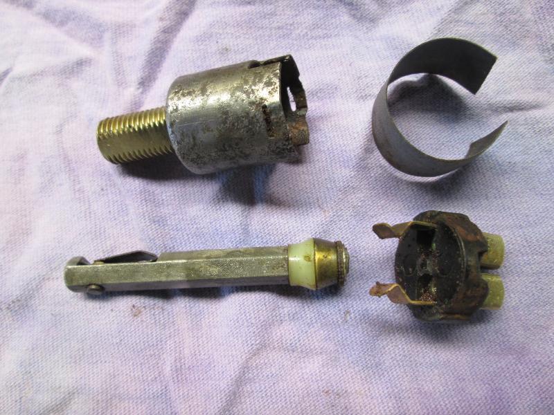
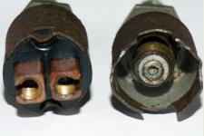
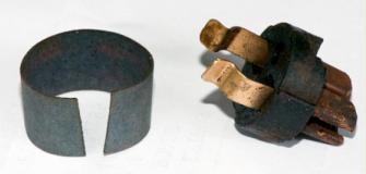
"Anatomy of a single pull Lucas switch. In the unlikely event that one of the single pull Lucas switches needs attention, this is what they look like when disassembled. The switch is held together by two crimped sections at the base. Once these are pried open, the Bakelite block can be wobbled out this one was quite tight".
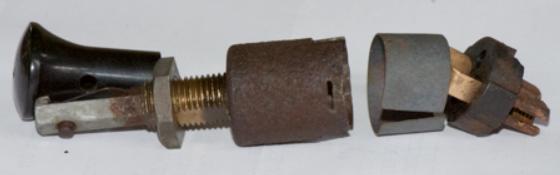
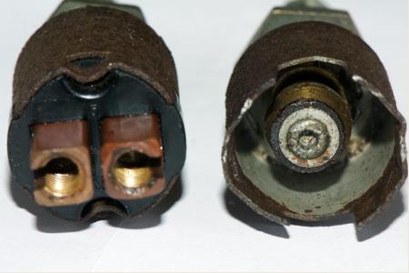
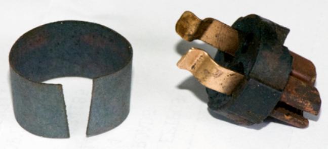
"There are two copper fingers/contacts on the Bakelite block, insulated from the body by a ring of thick grey paper. There is a brass central contact riveted to the shaft so that when the knob is pulled, it contacts the copper fingers of the Bakelte base. Looking at the structure, the most likely thing to go wrong is dirt interrupting circuit. The contact points can easily be cleaned with a cotton bud without further disassembly. The central contact is riveted to the inner end of the switch shaft and may be difficult to reassemble if removed. -- Reassembly is the reverse of above".
Note from Barney:
These are "gross motion switches", meaning that the moving contacts slide across the fixed contacts. They are therefore self cleaning in normal service. If the switch is left idle for some years, the contacts may become somewhat corroded and lose electrical connection. The common cure for this malady is to simply operate the switch about a hundred times to rub the contacts clean. These parts are normally very robust. All three of these single pole switches in my car are original issue and still working well after 63 years and 620,000 miles.
Addendum March 20, 2021:
Greg Reynolds adds these photos and notes:
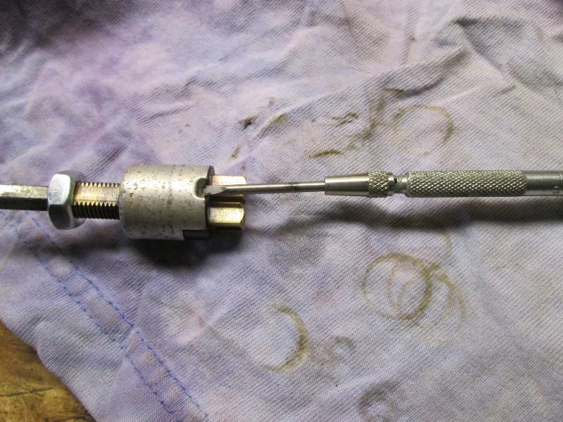
"Reviving 27H5278, the pull switches for the wipers, map light and fog lamp. Carefully lift the crimps holding the metal body (either aluminum or iron) to remove the bakelite base and the contacts. Depress the knob retaining button and push the stem out the back of the switch body.

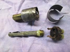
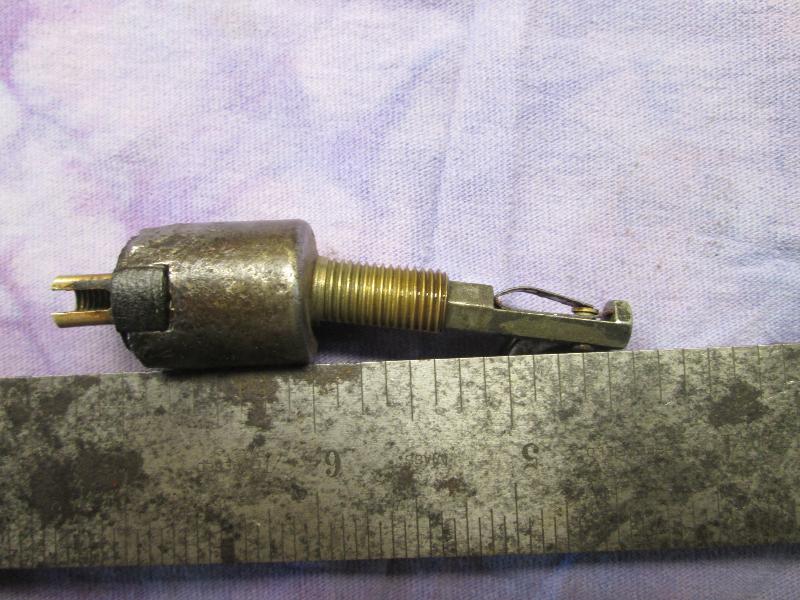
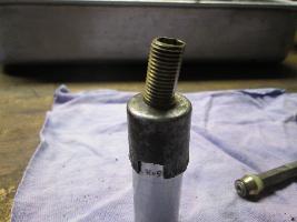
If the stem is not lined up with the body, use a deep 1/2-inch socket as an anvil and a 7/16-inch socket works for a punch. Tap the high side of the body at the base of the threaded neck to bring it back square.

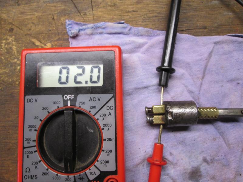
 Soaking the contacts in vinegar will soften the tarnish and make it easy to clean off. Polish the contact on the base of the stem with a piece of Scotchbrite and give it a little coat of conductive grease, and it is ready to reassemble. The button on the stem goes toward the side with the flat on the on the threaded neck. Don't forget to reinstall the paper sleeve before you recrimp the body to the base. Check your work. My DVM has a hard time measuring zero ohms but this is it.
 Do not use a 10-32 screw in the binding posts without at least putting a taper on the end of the screw. A square cut screw bottoms out before the wire is securely clamped in the post. Continuing to try to tighten the screw only leads to grief. Peter at BSA Unit Singles in NH has 2BA hardware and binding post screws". Do not use a 10-32 screw in the binding posts without at least putting a taper on the end of the screw. A square cut screw bottoms out before the wire is securely clamped in the post. Continuing to try to tighten the screw only leads to grief. Peter at BSA Unit Singles in NH has 2BA hardware and binding post screws".
Note from Barney:
The brass contact cone at back end of the shaft is electrically isolated from the shaft by a nylon bushing and fiber washer. If the nylon part would break, the switch could short to ground through the shaft to the dash panel. The brass contact cone, nylon bushing and fibrer washer are secured with a steel flat washer and peened over end of the shaft. Attempting repair of this part would require grinding away the riveted end of the shaft, after which reassembly may require drill and tap to install a small machine screw. I hope you have plenty of time and patience if you would do that.
|