The MGA With An Attitude
HEADLIGHT RELAYS and FUSES - ET-206A
By now you may know I'm not a big fan of installing unnecessary relays or fuses. However, there are times when a relay is absolutely required, and a fuse may be handy to install at the same time. By the book, the original Fog switch and wire from that switch to front of car is only intended to supply power for a single fog lamp or single driving lamp. If you install more than one lamp you must use a relay and larger supply wire to carry the increased current load. By popular demand I am posting this article to cover a multitude of issues involved with installing fog lights and driving lights, adding relays and fuses to the lighting system. Hopefully I can make one schematic cover all the bases, along with some notes on various options.
Before going any farther, PLEASE be sure to review "Lighting Upgrade Regulations" in ET-204 (and try to resist doing anything illegal).
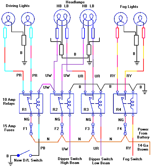
I do not show here the original connections of Lighting switch and Fog lamp switch, because nothing changes and you don't need to touch those switches. This setup adds four relays, four fuses, and one new dash switch for Driving Lights.
Consider the issue that for a long time asymmetrical lighting has been illegal in North America. There may be some exceptions if it was original issue from the factory when the car was built (at a time when it was legal). There may also be an exception if the asymmetrical lighting was installed as a dealer or aftermarket accessory during the same time frame (grandfathered in the law). This is how you might get away with installing a single 9-inch Lucas Flamethrower driving light, because it is widely recognized as a period accessory. To conform to symmetrical lighting laws you need to install new lamps in pairs, in which case you must use a relay.
Also consider that for a long time it has been illegal to use 100 watt headlights on public roadways in North America. I think the only exception to this might be if they were original factory issue as standard equipment on some cars, not including any add-on accessory lighting, not even if it was a period accessory. That means, not on MG's. Vintage incandescent headlamps as standard equipment used to be mostly in the 35-50 watt power range. Modern (cheap) halogen sealed beam headlamps are commonly in the 45-60 watt range, and sometimes 65 watts (with slightly shorter bulb life). Assuming you do not exceed 60 watts pre bulb, then (2x60W)/12V=10 Amps. This is why my schematic calls for 10 amp relays. Fuses are called as 15 amps, as a fuse or circuit breaker should be rated at least 20% higher than the expected load to avoid blowing the fuse in normal use. If for any reason you do install lamps greater than 60 watts, then up rate the relays and fuses and wire size accordingly.
It is required by law that you dip your headlights for oncoming traffic. Driving lights (not fog lights) are considered to be supplementary high beam headlights. So it is also required that the driving lights must be connected in such a way that they will go off when you dip the headlights. This is shown in my schematic, and there is more than one way to accomplish this. I will cover a couple of alternatives later (if I remember to include the options in this article).
If switches and wires and connectors were all properly sized for the current to be encountered there would be no need for a relay. The original equipment does not include relays, and these cars have survived quite well for decades without them. When upgrading lighting equipment it is prohibitively difficult to tear apart and rebuild the original wiring harness to increase wire sizes. Original switches may also not handle the intended increase of current. The primary reason for using relays then is to conduct more current than the original switches and wiring were designed to handle. The relays will allow installation of some larger wires without tearing the original harness apart and without overloading the original switches.
The basic formula for installation of a relay is to put the relay in between the switch and the load, and use the original switch only to trigger the relay. Then run a larger power supply wire from the battery to the relay to bypass original harness wiring. If the load device(s) can be connected directly to the relay, and original wiring between the load and the relay is adequate to carry the new current, then you may not need any new wires between the relay and the load. This is why a lighting relay will commonly have dual output terminals, so you can connect two lamps directly to the relay. If the two lamps were joined with a snap connector, and you have only a single wire from that connector to the relay, then that wire would be carrying double the current, which may require using a larger wire for that conductor run. Remember one 60 watt lamp draws only 5 amps at 12 volts. As such, placing the relay(s) near the location of the original load wire split may reduce the number of new wires needed.
For the MGA that approach might call for placing the relay(s) in a rather inconvenient service location in a blind corner forward of the radiator. A more viable alternative may be to install the relay(s) on the inner fender aft of the radiator, and run some extension load wires from the relay to the load device connectors up front (in place of the original 4-way splitter snap connectors). In that case my schematic above would need 8 more wires and connectors between the relays and the original lamp connectors. Original type tubular snap connectors with bullet wire ends make two connections at each junction, meaning the 8 extension wires might result in as many as 16 more connectors. If you were sharp about what's going on here you might make up a new cross harness for the front end with longer wires to accommodate the extensions without needing the additional interim connectors.
As you add more lamps the supply wire gets larger and carries more current. The risk of a short circuit somewhere increases with the number of lamps and wires. The risk of a short circuit on the primary supply wire does not increase with wire size, but consequences of a short circuit on that wire or any of the following distribution wires does increase with the higher current carrying potential of the primary wire. As such it is prudent to install at least one fuse somewhere that may blow if there is a short on any of the load wires. The problem then is that a fuse carrying close to 30 amps expected load for 6 lamps would have to be at least a 35 or 40 amp fuse. That would protect the large primary power supply wire, but the smaller downstream distribution load wires might still burn with a short circuit without blowing the high capacity main line fuse. Solution then is to install multiple smaller fuses in line before the smaller wires.
If you are installing any fuses at all I would recommend separate fuses for high and low beam headlights, so that if something shorts and blows a fuse you may still have some light (better than no light). If you were a little creative you might wire in a "load shedding" circuit. You could hook it up so the fog lights and driving lights cannot be on at the same time, reducing maximum total load to 20 amps rather than 30 amps. If you think about it a little more you might set it up to kill the high beam headlights when the driving lights are on, reducing that combined load. If you set it up so only one pair of the three sets of lamps can operate at any time, then the primary wire only needs to be large enough to carry 20 amps, and you could get by with a single primary fuse. But that gets back to the possibility of having no lights as all if a single fuse was to blow.
Once you commit to physically installing at least one relay and at least one fuse, the additional relays get to be successively easier to install at the same time, and additional fuses look very simple by comparison. If you assemble all of the relays and fuses on a single mounting platform (good for serviceability) it is likely easier to use one fuse with each relay rather than mucking about trying to figure out how to eliminate one or two fuses. Similarly, it is probably easier to install a larger primary supply wire than to incorporate a load shedding circuit. If you were really nuts and wanted to fuse each headlamp filament separately you could install eight fuses after the relays rather than four fuses before the relays.
You may notice that my schematic calls for using the original harness wires from the dipper switch and fog switch, and original wires from the relays to the headlamp high and low beams. A single fog lamp (or single driving lamp) distribution wire was always an add-on along with the single lamp. So all distribution wires from the relays to the fog lights and driving lights are additions along with the lamps.
There is one of these "cat skinning" logic tricks where I suggest a short jumper wire from high beam relay output to driving light relay trigger coil, then ground the new driving light switch. This will kill power to the driving light relay trigger and kill the driving lights when headlights are switched to low beam, even when the driving lights are manually switched on. The alternative to that is to ground the driving light relay trigger coil same as the other relays, trigger the DL relay from the DL switch, and tap power for the DL switch from the dipper switch high beam output. That choice leaves you to figure out how to run a new wire from the dipper switch high beam output to the new DL switch, where I find it easier to ground the DL switch.
You could incorporate a similar trick for the fog light relay by connecting the trigger coil to the power input terminal, then grounding the Fog switch. This is a preliminary step toward defeating the fog lights when driving lights are on. You could do that by using a double throw relay for driving lights, and using the normally closed output terminal to power the fog light relay trigger coil. Then the fog lights would only work when driving lights are off, and the load shedding function requires nothing more than a double throw relay in place of the single throw unit.
My diagram adheres to the KISS principal with four relays and four fuses, and I would defy anyone to find an easier way to do it (other than leaving something unfused). However, as I said in the begining, I'm not a big fan of installing unnecessary relays or fuses, so I consider how much of this relay package is not really needed. The headlight high and low beam circuits do have larger wiring as factory original issue, so those two relays are not really needed (as long as you do not exceed 60 watt bulbs). When it comes to dual fog lights or driving lights, rather than running a heavy buss power wire and an additional signal wire and relays to the front, it may be just as easy to run two slightly larger wires for lamp supply direct from the dash switches and forget the relays all together. If you do that you can install all the new fuses you like in a convenient new panel out of sight behind the dash. For discussion of how many fuses might actually be useful and where to put them see article ET-201B.
|