The MGA With An Attitude
Installing HIGH POWER HORNS - ET-208A
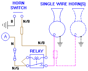
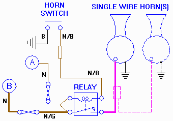
 You may recall this diagram from the prior page. There the primary purpose for the relay was to change power polarity at the horns to switch power going to the horns while the horns will be grounded on the chassis. Note that the power is still supplied through the original fuse and harness wiring, and the return wire to the switch is also as original. Also recall that the original fuse is a Lucas 25/50-amp fuse that will allow a continuous current draw of 20-amps through the original harness wiring without blowing the fuse. The original harness wiring (with or without the relay) can handle dual electric horns, or any other horn installation that does not exceed 20 amps continuous current draw.
For a quick reference, I have installed dual air horns fed by an instant-on electric air pump. This air horn kit came with a relay and an in-line fuse, and instructions to connect the fuse to the battery (main battery cable) in case original harness wiring would not carry enough current for the air pump motor. Instructions also called for use of a 20-amp fuse for the air horn setup, which means the new fuse and relay are not required in the MGA, as the original fuse and harness wires have adequate current capacity for the air horn. If your new horn calls for more then 20 amps current draw, then by all means install a new larger power feed wire and power relay.
If you wish to test the original wiring for a new high power horn installation, you can hook the new horn(s) up first to the original wires. Then connect a long heavy gauge jumper wire to the main battery cable and run it up to the area of horn mounting. Press the horn switch to sound the horn. While the horn is sounding, connect the hot jumper wire directly to the horn power input terminal. If you find an appreciable increase of sound volume, then a new heavier power supply wire and power relay may be beneficial.
 To install a larger power feed wire connect it to the main battery cable. The power input terminal on the starter switch is a good power source in the MGA. Install a new in-line fuse (of adequate capacity) as near as is practical to the power source point. Connect the new fat power feed wire to the fuse, and route it along the original wiring harness to wherever you chose to mount the new relay. Run another new fat power wire from the relay output terminal to the horn. Then connect the original browN/Black harness wire to trigger the relay. The original brown/green wire in the harness will then be left disconnected (at the horn end), and you can remove the original 25/50 fuse, or use it for some other constant-on application (like a car alarm for instance).
Note that the two original harness wires NG and NB run in a separate small branch of the harness from the right front corner of the car to the original horn(s). When installing a new power relay with new fatter power wires, the original small branch of the harness may be re-routed to the location of the new relay, so no new trigger wire is required.
|