The MGA With An Attitude
Thursday , September 4, 2025:
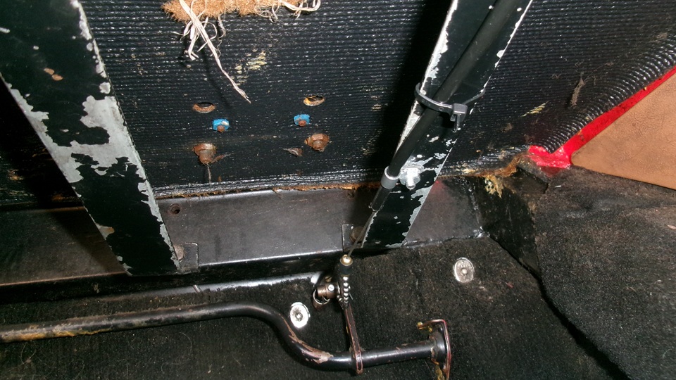
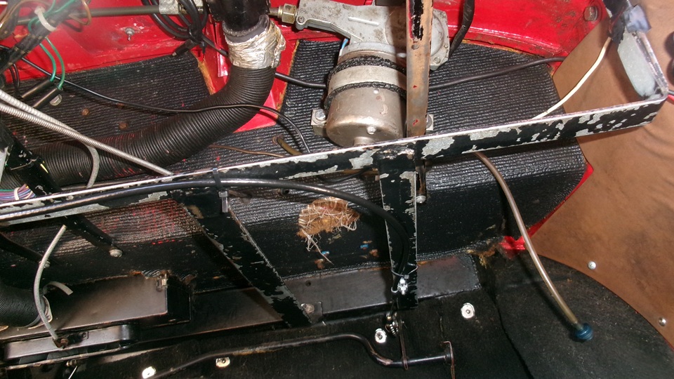
Thursday , September 11, 2025: We got on with installing the new cruise control servo that arrived Tuesday. This thing has at least 100 feet of small gauge wire with harness connectors and wire end connector terminals for most of the wires. There are also a variety of pull cable brackets and end connectors, and an instruction book bound to require at least a couple hours or careful reading to digest it. By noon we were hands on, mostly in the car, figuring out how we (I) wanted to do the draw cable output end brackets. Been here a few times before, trying things differently each tine. Not wanting to put more service obstacles in the engine bay, I decided it ll goes under the dash this time. Surprise! The draw cable was positioned to pull on the input end of the original throttle cable where it is attached to a trunnion at top end of the throttle pedal arm just above passenger's right foot (in the LHD car). The draw cable jacket would be anchored underneath the steel frame of the Navigator's Desk (which can be found in the Accessories Tech section). The servo unit (electronic, no vacuum) would be mounted to back side of of the bulkhead far left and high above driver's left foot.The draw cable would run left to right above most harness wiring and above defroster hoses. The idea is, only a few unobtrusive wires to run through the harness bulkhead grommet into the engine bay. The nasty part of this chore was working under the dash all day without removing the dash panel. At least a couple of stressful hours to get the draw cable connected. Only one small hole to drill in the Navigator's Desk frame to secure the P-clip anchoring the cable jacket. 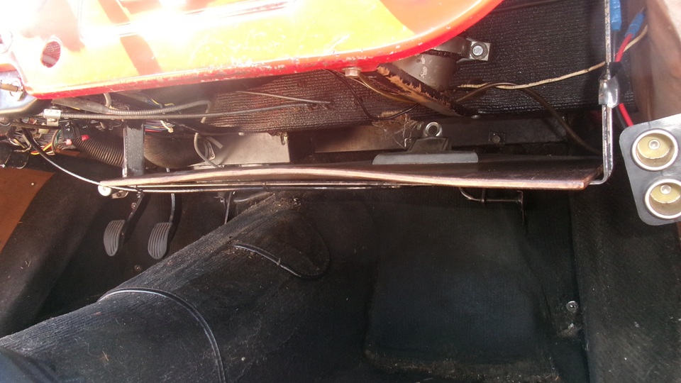 Photo at right is a view into the Navigator's desk from the rear (working end). This is a steel strap framework holding an 18-inch square sheet of 1/4-inch plywood with a pinch clamp for a clipboard. Easier to see with the board removed (pictures below). Front to back straps of the frame are attacued to the chassis frame goal post. The latteral shaft of the accelerator pedal passes under the N/D frame with the vertical pull lever at right end. This carries the trunnion that pulls on the throttle cable passing forward through the bulkhead panel below the goalpost. This trunnion is the point where I made the bead chain connection for the C/C pull cable. The pull cable jacket is secured to the bottom of the N/D frame with one P-clip and #10 screw and a few tie-wraps, then heading off to the left side where the C/C servo is located. We can clean up the frayed insulation pad later. In short, the C/C cable is pulling on the accelerator pedal arm, so it doesn't have to be connected separately to the carburetor throttle lever. That is, no new C/C parts in the engine bay. But you do need to get used to the accelertor pedal moving when the C/C is working.
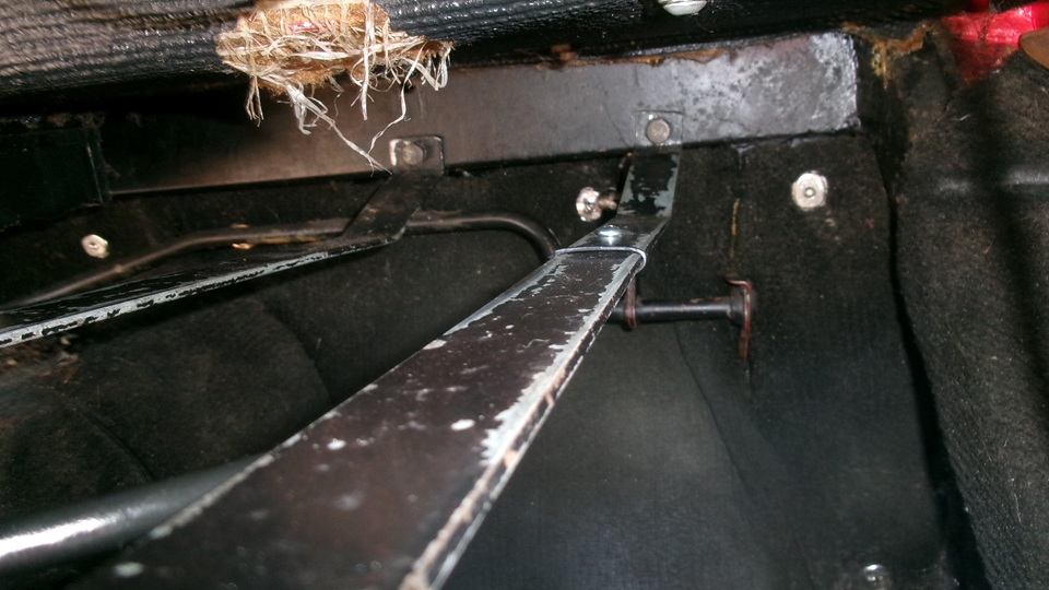
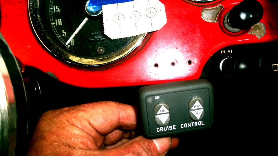
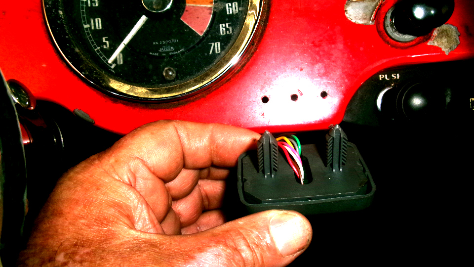
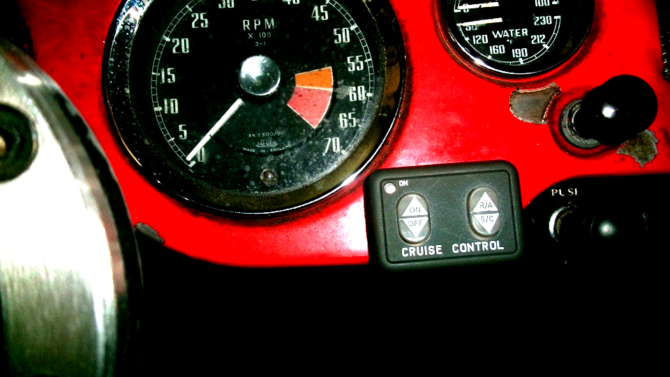
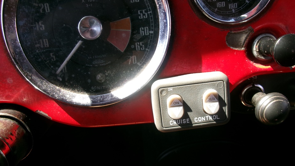
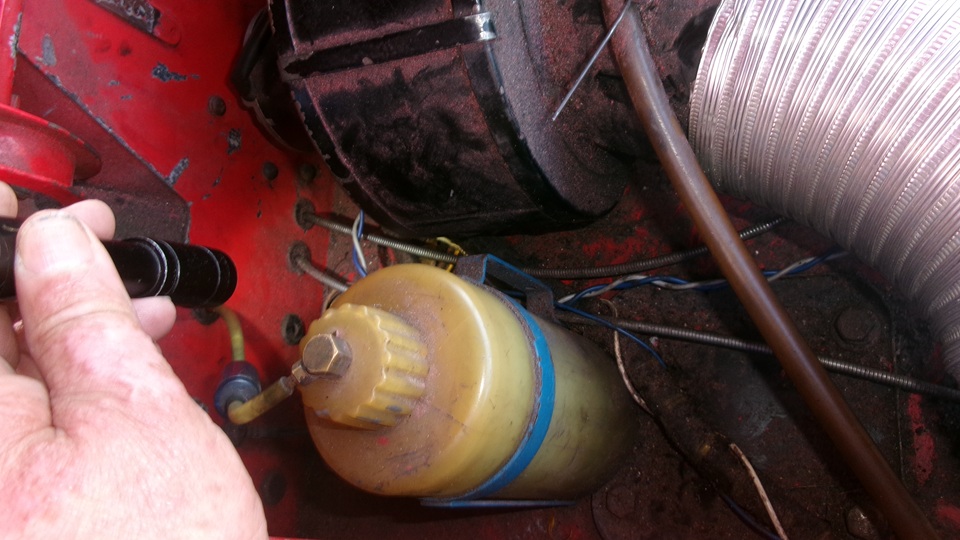
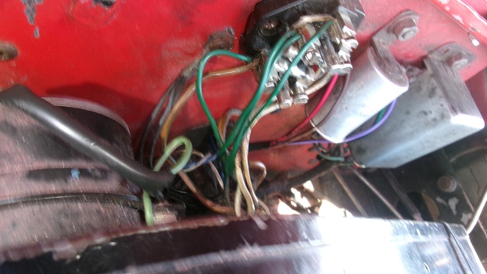
 On the other side, we soon removed the steering wheel for better access underneath. The C/C kit included a nice mounting bracket for the serve unit, that must be the result of 20 years experience, very nice. It looked rather like a large box end wrench with offset working end, and a line of holes in the handle part to attach where convenient. This would fit nicely using the top bolts for the master cylinder bracket. We just needed to elongate two of the holes slightly to fit the bolt centers on the firewall. Aside from crawling under the dash repeatedly for trial fittings, the deed was soon done. Having expended enough cursing and scratched knuckles for one day, it was time for dinner and some well deserved rest. Friday , September 12, 2025: With stuff physically mounted in the car, today was the day to connect all of the wiring. The C/C servo unit fits nicely in the upper left corner of the bulkhead The servo module is attacued to rear of the firewall, above driver's left knee, and just above the bonnet latch release pull handle. You can see two hex nuts securing the servo bracket to the top two bolts of the master cylinder bracket. To right of the hex nuts, the servo pull cable carries the white number tag. Then photos of the control switch front and rear. The switch has a green LED for power "ON". There is no indicator light for "Engaged", but you don't need any lamp to tell you it is working. That lamp is optional with different c/c model.The rocker switches are backlit for night driving, with the internal lamp connected to the Panel light dimmer switch, and it works. There is a 4-color harness with black tape running from the switch toward the control module 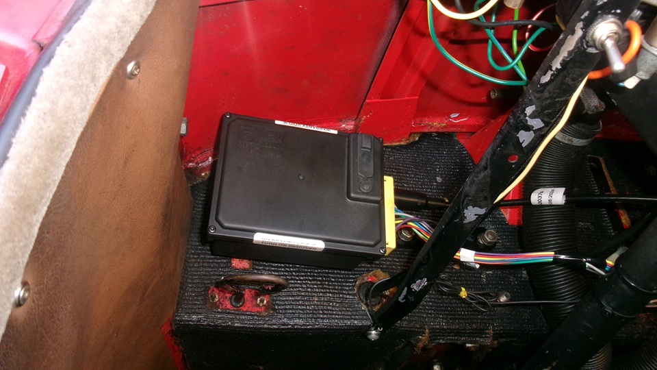
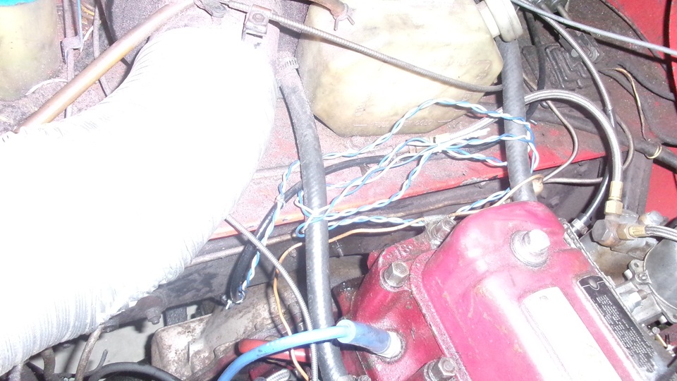
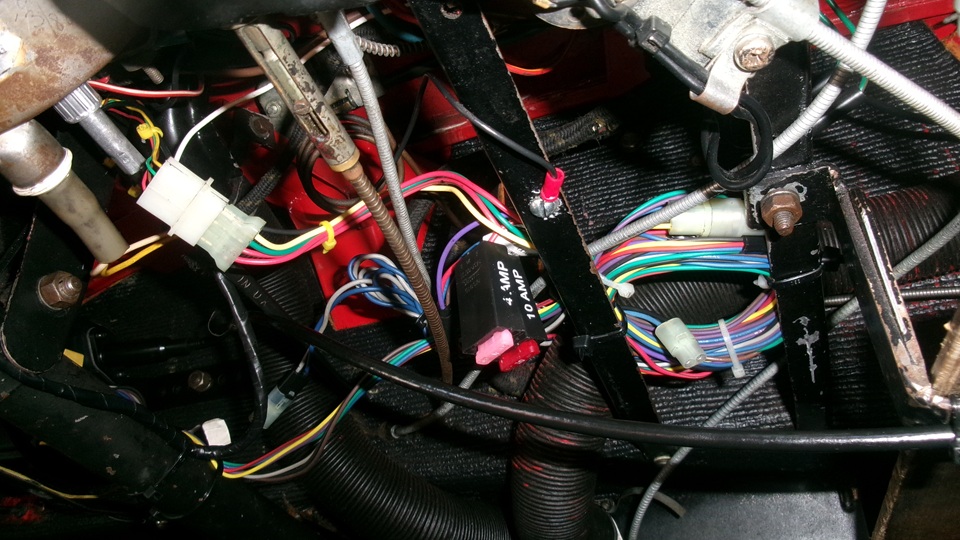
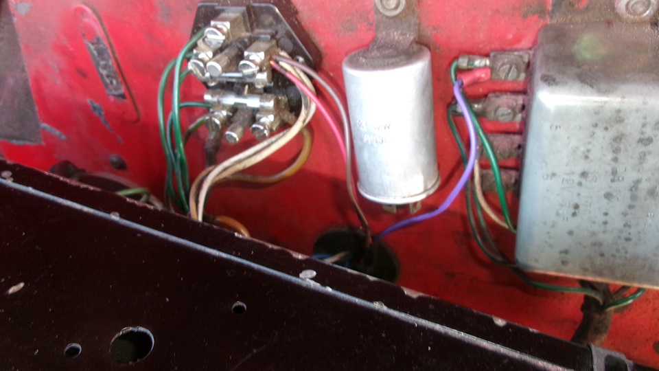
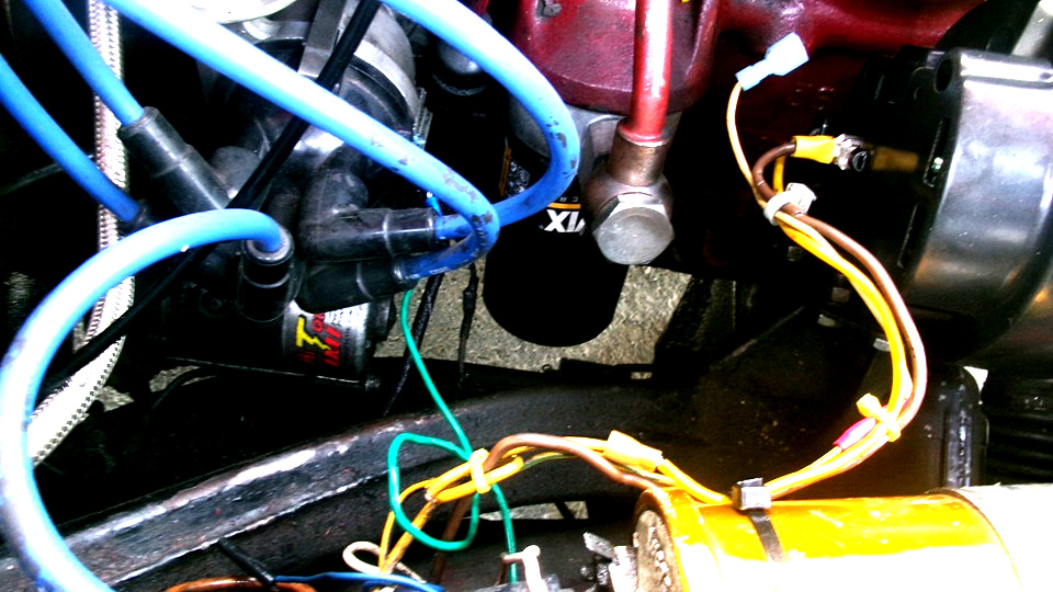
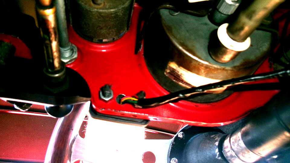 Everywhere there is black tape in this system, the tape will fail,loose and unwind itself if you touch it, or even by gravity alone. Apparently the first time the tape gets warm it fails, and when loose it feels gooey but has no stick. The only way to keep it from falling off is to put put tie wraps around it, or maybe tie a knot at the end. There is a harness connecting the servo to the control key panel, a few wires to back of dash, and few wires running through a grommet to the engine bay. Also two wires from the speed sensor magnet coil under the propshaft running up the speedo drive cable , around the heater box, through the bulkhead grommet, to plug into the servo harness. It sounds easy enough to plug in a few connectors and connect a few bare wire ends, but try doing this while crawling around under the dash with no space to reach hands through. The white connector with four color wires is the connection between the switch and the servo unit (black tape replaced by little tie-wraps, more for strain relief). Two blade fuses, 10-amp for the servo unit (Brown wire) is connected to White wires terminal of the fusebox, powered with ignition switch on. 4-amp for the switch input (Red wire) is supposed to be connected to "Brake Hot" which is a green wire fused ignition source. But that would be a redundant series fuse, so I connected this one also to the Whitewire termimal of the fuse box. There is a Violet wire to be connected to "Brake cold" or Brake Negative", which is the output side of thhe brake light switch. In the car this is a Green/Purple wire. For the 1500 model it runs to terminal 5 on the turn signal relay box. Easier access to connect this Violet wire to the relay box rather than running to the brake switch. So I have Brown, Red, and Violet wires running through the bulkhead grommet two connect to fusebox and one connected to the turn signal relay. Last picture below, pretty unobtrusive in the engine bay. On further consideration, the two power feed wires are connected to switched ignition, which could have connected under the dash, and didn't need to be in the engine bay. 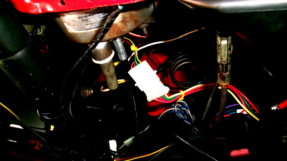
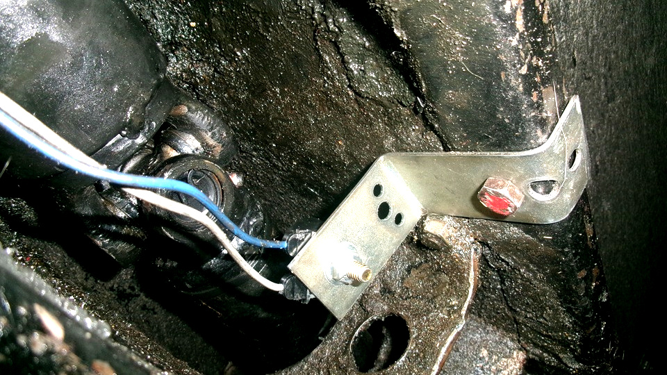
 There are the Blue and White twisted pair wires from the propshaft magnet sensor (installed the week before). These run along the speedometer cable, up past the gearbox bellhousing, onto the heater shelf, around the starboard (right) side of the heater box, then behind the heater box to pass through the large rubber bulkhead grommet, then plug into the C/C servo harness. This routing is installer's choice (for now). Alternate could be to pass through the tunnel wall close to the magnet sensor coil, then run through the interior (under the carpet) to get to the C/C harness connector behind the dash. That would keep these wires out of the engine bay. I may yet find a way to eliminate need forthe magnet speed signal device (if I can solve the problem of valid TACH signal source. 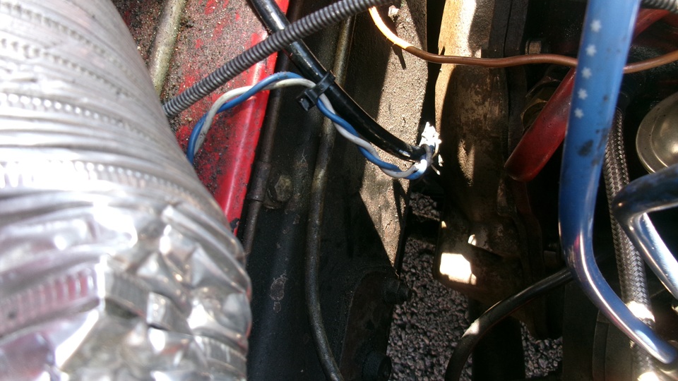
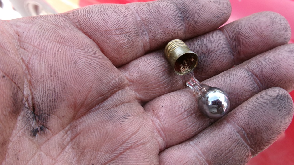
 When it was all electrically connected, there was at least six feet of the new harness lying across the left door threshold on onto the garage floor. This would eventually get coiled around my hand to make a tight fat coil to be tie-wrapped together and stowed/tie wrapped on top of the two center lower dash braces. A couple other lengths of loose harness got similar treatment. A few more tie wraps to tie up anything hanging loose. When finished there are two in-line blade fuses hanging down just left of the steering column for easy access (likely never to be needed). That was another good stopping place to call it a day, go have dinner and chat about progress. We didn't want a test run until we had more time to deal with any contingencies. Saturday , September 13, 2025: Up fairly early for breakfast, waiting for morning rain to stop, and to "close up shop". Clip off and toss out the old turn indicator warning lamp. Break out the new Green LED dash warning light. Drill out the 9-mm double-D dash mounting hole to 5/16-inch . Then install the new Green LED, connecting it to the original signal wire, and grounding the second wire. Reinstall the steering wheel. Pick up. clean up, pack things away, put the bonnet back on the car. Then off for a test drive. Engine ran fine, got it out onto some rural side roads, up to 40+_MPH. switch on the C/C, and bush the Set button. A few seconds delay at first, and then it took up the slack and began working, somewhat. The button functions didn't work exactly as I was expecting, but once we figured out how it wanted to work it went better. Got it to work normally in top gear at speeds between 45 and 75 mph. Also for slower speeds, decreasing in 1-mph increments down to 25-mph before it dropped out. Also we figure the single magnet pulse sensor on the propshaft as recommended was working well enough at 3180 pulses per mile. There were a few instances when it wanted to surge, speed up a bit too fast, the slow down a bit too slow, and repeat. On one occasion it dropped a few MPH and continued, dropped a little more and continued, repeat a few times before dropping out. This seemed like a surge condition that might be damped out with adjustment of few dip switches, maybe later after we get more experience with operation. For now, good enough to point it east and haul out of town. 95 miles east on US 30 in 1-hr 40-minutes, stopping in Fort Wayne, Indiana for fuel and late lunch. Some problem running more that 10 minutes at a stretch before it would drop, serge a few times, then drop out. Get back up to speed and hit the SET button, and it was back to cruising again. -- Having done this a few times, I was getting the idea that it might be seeing a conflict of two different sped signals. We had connected the TACH wire to the points side of the ignition coil, as this was supposed to enable over-rev protection in case an automatic gearbox might be knocked into neutral while under power, or if the clutch pedal might be depressed while under power. The over-rev drop out function didn't work, so when we stopped for fuel we decided to try disconnecting that TACH wire from the ignition coil. There was some information with the cruise control instructions implying that it might not work if we had LED bulbs in the tail lights. Seems like the brake light switch output side, which is normally disconnected when not braking, may be used by the C/C to verify ground connection, or the fact that the bulbs are actually in place so the brake switch C/C kill function can work. Bit of a stretch. LEDs have high resistance, so may look more like open circuit when at rest. This might be a good time to begin swapping in some LED bulbs. Front lamps are easier, just push/twist to remove the lens. Passenger side was easy, and the new Amber bulb us bright and clear. Peachy. Driver side not so easy with the fixture so corroded that the bulb could not be removed. So we need to buy another new lamp assembly, and meanwhile do not disable the existing lamp. Score one Amber lamp only, and leave the rear bulb swap for later. I will update this again later, after we get a chance to try led bulbs in the rear. We headed east again late night. Another 105 miles in 1-hr 40-min took us to Upper Sandusky, Ohio by 10:45-pm, Good news this time, the C/C worked flawlessly, no surging or cut-outs. We caught a semi by the tail doing 69-70 MPH and just followed him. Dropping back a little after 10 minutes, click +1 on the speed button. Closing the gap some after another 20 minutes, punch -1 on the speed button. The semi must have been on C/C as well, as this continued for the rest of this leg of the trip. More than 90 minutes of flawless C/C operation, so it seems I must have been right about the conflicting speed inputs. Whenever we get confident enough, we may try unplugging the magnet speed sensor, and reconnecting the TACH wire to the ignition coil. If that would work, we may have speed sensing of engine rather than wheels, and also maybe the over-rev cut-out function might work. If so, then it may work as I had originally intended, and it wouldn't need a clutch switch. Time will tell. Tuesday, September 16, 2025: Quick pit stop and head out early morning, another 75 miles before a fuel stop in Reedsville, PA, just a splash and dash. Then having more Cruise Control problems with abnormal cut-outs. Navigator noticed the plug-in volt meter dropping to 0-volts, blinking off and back on again every tine the C/C glitched out. ,and sometimes the alternator was charging or not charging. Hint. Look for loose wire on the alternator. Stopped in Milesburg, PA to check the alternator first. Sure enough, broken wires from the alternator (again). Long story short, we repaired three alternator connection wires, and also had to change a burned out light bulb in the ignition warning lamp, becsuse the alternator will not work without the warning lamp being connected. Then it was charging again, and the cruise control was working again, flawlessly no less. 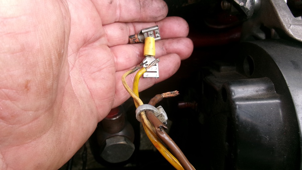
 Tuesday, October 7, 2025: Two weeks past, sitting in Winchester, MD this morning.We still need to check to see if the C/C will work with LED brake lights in the circuit. Change the dual filament rear bulbs from incandescent to LED bulbs. Tail lights work, Brake lights work, turn signals and 4-way flashers do not work. Try two more different electronic flasher units, still no flashers. Getting frustrated, no more time to waste today, so put the incadescent bulbs back in the rear so erything works, and forget the C/C test on LED bulbs until later.Check back later for more results. For a typical cruise control installation instruction sheet, see: |