The MGA With An Attitude
FUEL SENDER REPAIR -- ET-214
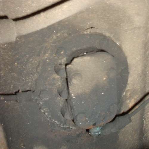
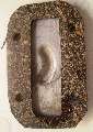
 The fuel sender unit is located on the right side of the fuel tank, just inboard of the right rear wheel on the MGA. So initial approach is to jack up the right side of the car and remove the right rear wheel for easy access. Don't be surprised if it is quite dirty like this picture, and do take the time to clean it up some before disassembling anything.
Before you start fiddling with the fuel sender unit, you should check to see if it works. Disconnect the signal wire and use an ohm meter to check resistance between the signal terminal stud and the body of the sender unit (which will be grounded on the tank). The MGA sender should show resistance of about 70 ohms when the tank is full, and zero ohms when empty, and the resistance reading should be proportionately linear in between depending on the amount of fuel in the tank. If it ain't broke don't fix it.
Another important thing to check is the resistance between the fuel tank and the frame of the car. The sender unit needs a good electrical ground connection to operate. The fuel tank is mounted in rubber lined straps, and the filler pipe is connected with a large rubber hose, so the tank may not be directly grounded to the chassis. Originally the tank was connected to the fuel pump with a steel pipe, and the fuel pump had a ground wire connection to the frame of the car. Many aftermarket fuel pumps will be connected to the steel fuel lines with rubber hoses, which can break the ground connection for the sender unit. Use the ohm meter to check resistance between the fuel sender unit mounting screws and the frame of the car. This should be very close to zero ohms (less than 1/4 ohm). If you read higher resistance here, then install a ground wire connected between one of the sender mounting screws and the tab on the frame nearby (which should be holding a P-clip for the wiring harness). If you get that far and the resistance reading is correct, then leave the sender unit alone and look elsewhere for your fuel gauge problems.

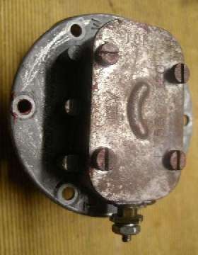
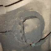
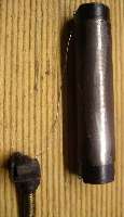
 As the fuel sender unit is mounted on the side of the fuel tank, you wouldn't want to remove it when the tank is full of fuel. It would be good to drain the tank first, especially if you contemplate having it opened up for a prolonged period of time. But for an anticipated short repair it could be okay just to run it down to a couple of gallons of fuel (less than 1/4 full) before unplugging the large hole in the end of the tank. If it has a little more fuel, up to 1/2 tank or so, then it might work to jack up the right side of the car to let the fuel flow toward the left side of tank. When in doubt, remove one of the bottom mounting screws first to see if any fuel will run out through the threaded hole. When the fuel level is low enough, you can disconnect the signal wire, remove the six mounting screws, and pry the unit free from the gasket surface. Once removed it looks like the pictures at right.
Once the sender unit is free, you should immediately check to see if the float actually floats. The original float is a brass cylinder soldered together for an air tight seal. If it springs a leak it can fill partially with fuel. The float should be light weight, and when shaken it should not slosh. If you feel or hear fuel sloshing inside of the float it will need to be repaired of replaced. Sometimes a leaky brass float may be repairable, depending on why it leaks. If you place it in a pan of boiling water the fuel inside of the float will eventually boil off and steam out from the leak point(s). You then need to remove the float from the boiling water before allowing it to cool. If allowed to cool while still in the water, the gas vapor inside the float will condense creating a vacuum inside, which will draw water into the float. Even if there is nothing but air inside, cooling will cause the air to shrink, which will in turn draw water into the float. Once the float is empty and cool and dry you may attempt to seal it. If the leak is at a solder joint you may be able to re-solder it to seal the joint. If a brass float has a crack it will not be repairable, and again you get to see how far you can throw it.
Some aftermarket units may use a plastic float, most commonly light and solid, not hollow. These foam plastic floats may sometimes become saturated with fuel and can sink. If a plastic float does not float, see how far you can throw it and get a new one.
The first key to success of fuel sender internal repair is knowing how it works and what is inside before you take it apart. You don't want to bugger up something simple (like breaking a hair size wire for instance). The sender unit is NOT sealed on the inside, and it will operate with some fuel inside, so when you remove the outer cover be prepared for a possible small amount of fuel spillage.
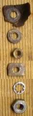
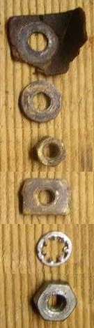
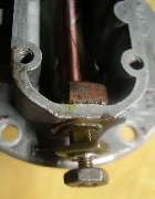 With the cover removed it will look like the picture at right. The fastening hardware on the bottom contact stud is shown at far right. From bottom up there is a hex nut (not original type), a lock washer, sometimes a flat washer (not shown), a square nut (jam nut), a hex nut, a flat washer, and an insulating washer. The threaded brass stud also has an insulating collar where it passes through the bottom of the sender shell, and another insulating washer (or phenolic block) inside the shell. These insulating washers may be just a thick piece of hard paper, or they could be fiber washers. The important points here are that the stud must be electrically isolated from the case, and it must ultimately be sealed to prevent fuel leakage. Remove the various washers, nuts and finally the insulating paper. Carefully push the bolt into the sender unit being careful not the break the thin copper wire attached.
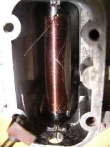
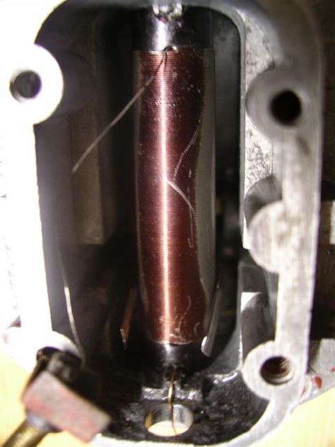
Inside you will find a cylindrical spool with a single layer of very small wire wound onto it. Click for a larger picture, and you can see mechanical wiper contact arms on both sides of the coil (near the bottom of the spool). At each end of the winding the wire is run through a hole in the spool to secure the wire.
The wire end from the top end of the spool is connected to the threaded signal stud. The wire end from the bottom end of the spool is simply tucked into a hole near the end of the spool to secure it (not electrically connected). Electrical current flows from the signal terminal to the top of the coil, then down through the wire coil to the point where a moving wiper arm touches the side of the spool. From there the wiper arm shorts the current to the body of the sender unit, and no current flows in the wire below the wiper arm contact point. The working resistance of the sender unit is the electrical resistance in the coil above the wiper contact.
To remove the coil from the case you can loop a wire around both ends of the spool and pull it forward parallel, both ends at the same time or with a slight rocking action, until it comes free of the case.
If you are thinking of rewinding this spool you will need to very carefully measure the wire diameter with a micrometer, and also count the number of turns of wire as you unwind it. To have the proper electrical resistance this is enameled resistance wire (not copper). You may have to procure the stuff from an electrical supply house. See additional notes about the wire alloy in Addendum below.
One aftermarket unit was carefully measured for wire size, being 0.0105 inch (including the thin insulation). This makes the following wire gauge numbers:
0.0100 - 30 AWG - American Wire gauge
0.0104 - 34 - US Steel Wire gauge
0.0100 - 33 - British Standard Wire gauge (Imperial Wire gauge)
0.0100 - 31 - Birmingham or stubs Iron Wire gauge
This may give approximately 120 turns of wire on the bobbin in the space allowed (but not counted yet). For rewinding it should be sufficient to simply line the bobbin with a single layer of closely packed turns filling the distance between the cross drilled holes (assuming you use the correct wire size). This should yield a coil resistance slightly higher than 70 ohms. Winding might be most easily done by chucking the bobbin in a slow turning electric drill and guiding the wire to keep it tightly packed while winding. Tuck the first end of the wire into one of the cross holes, wind along until it reaches the cross hole at the other end, and finish by clipping the tail a few inches long and threading it through the second hole.
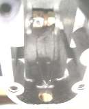
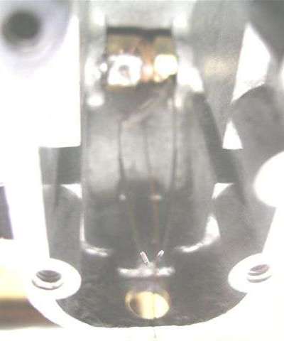
Here with the coil removed you can see the mechanical wiper contact arms (faint and blurry near center at bottom). These arms are formed to wipe along the sides of the coil and to make electrical ground contact. The wiper is driven in an arc by the rotating shaft. On the shaft is a hexagonal brass fitting with a round turned center section. The right side of this fitting is keyed to carry the wiper arm securely, and the assembly is also keyed to the shaft (tight press fit).
 There is a small copper grounding wire connected to the brass fitting (secured at the end). This wire is loosely wrapped three or four times around the brass fitting, and then runs down to the bottom of the housing (with a slack loop) where it is to be trapped under the bottom end of the bobbin for grounding on the housing. As the wiper shaft moves the grounding wire flexes like a coil spring to have very long life without breaking.
You can remove the float arm by tapping on the short end of the rod. It is a light press fit in the axle shaft. The shaft has only one end exposed on the outside with the other end in a blind hole. It would be difficult to withdraw the shaft, but generally not necessary unless the wiper arm assembly was damaged. If you remove the shaft be sure to reassemble it in the same orientation relative to the wiper arm, so the wiper will retain the same original travel in both directions.
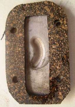
For the outer cover there is a cork gasket. When using a closed cell cork gasket it should not be necessary to use any adhesive or sealer. If you do use sealer it absolutely must be fuel proof. If the fuel can dissolve a sealer it can ultimately cause the joint to leak. It will be best to use a cork gasket and no sealer at all, assuming it will not leak when assembled.
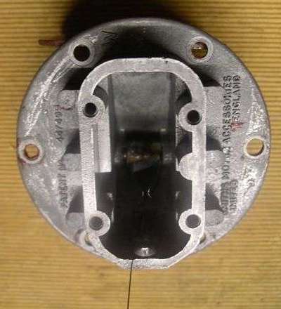
 If you use a thick paper gasket you probably would have to use a sealer, in which case I do not envy your problem. The paper gasket is an occasional downfall of some aftermarket parts suppliers. If you get a paper gasket (or two) for your sender unit, do consider cutting your own gaskets from sheet cork gasket material. Note that the screws holding the cover go into blind holes in the case, so you do not have to worry about these threads leaking. Also notice that the cover may say "TOP" at one end on the outside. The hole pattern should be slightly asymmetrical so it will only align properly one way.
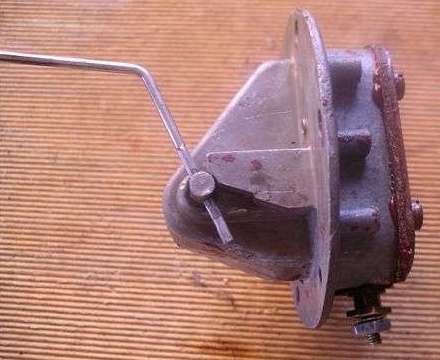
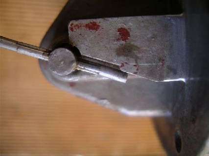
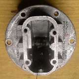
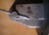 During reassembly care needs to be exercised refitting the float arm. It needs to be fitted so it passes a step on the sender body (see picture). Otherwise the wiper arm inside will travel too far.
The resistance coil can be gently pressed back into its mounting by hand, trapping the copper grounding wire under the bottom end of the spool for good electrical ground connection on the housing. Care should be taken with the placement of the internal signal wire (from top of coil to the threaded terminal post) so it does not foul the moving coil contacts. It is best the leave a generous loop in the wire. Upon first assembly with a newly wound coil it may be necessary to gently scrape the sides of the coil to remove the enamel insulation where the wiper arms will make electrical contact with the coil.
When replacing the sender bolt be sure to arrange the insulator parts properly to electrically isolate the stud from the case, and make sure it has a good seal with the case to prevent leakage. Sticky sealers are NOT recommended, because various additives in modern motor fuel may attach a wide variety of sealants. If you feel inclined to use a sealant it must be completely fuel proof.
After assembly test the unit to ensure a resistance of 0 ohms at full drop of the arm and about 70 ohms at full lift with smooth and near linear progression of resistance in between.
When refitting the sender unit to the fuel tank, it should be possible and functional to use a cork gasket with no sealer. Since the threaded screw holes pass through the wall of the tank into the interior, it is required to seal around the shank of the screws. Here the holes in the cork gasket should be about the same size as the screws, so that when the screws are tightened and the gasket is compressed it will be squeezed against the shank of the screws to affect a seal.
If you have a heavy paper gasket, you should seriously consider making your own gasket from cork gasket sheet stock. If you use any type of sealer for a gasket it absolutely must be fuel proof. If the fuel can dissolve the sealant it can cause a fuel leak, even if the sealant was used with an otherwise good cork gasket.
If you have a synthetic elastomer gasket, you might try using it at your own risk. Various additives in modern motor fuel may attack a wide variety of elastomers. In recent times there have been numerous problems with "rubber" parts being made from the wrong materials, so please be aware of this and check the gasketed joint periodically during use.
There are a few reasons for failure of a sender unit. If the car has been sitting for a long time with low fuel level, leaving the sender unit exposed to air inside the tank, then the pivot point for the shaft may be corroded. In extreme cases the aluminum shell might be corroded inside, and products of the corrosion may accumulate to fill a large part of the normally empty space inside. A most common reason for failure would be a broken wire inside. The wire used internally is very thin and could be broken by long term vibration or by wear from the moving contact wiper arm. If the signal connection stud should work loose from the housing and move around a bit, or if it happens to get twisted about while working with the wire connection fasteners, then the small wire inside may also be broken or might be shorted to the housing. If the insulating parts around the connection stud break down the stud itself might be shorted to the housing. In rare cases the moving contact arm inside might be bent or lose its spring force and may lose contact with the coil. Once you understand how the sender unit works it should be easy to find the fault, and not too difficult to repair it.
Thanks much to Russell James Goebel for the pictures, the initial mechanical work to take the pictures, and his description of the parts and some problems encountered.
Addendum April 27, 2005:
Having just finished an update on resistance wire winding in the fuel gauge (previous page), I can include similar notes here. Not having the actual numbers at hand, I estimate the bobbin to be about 3/8 inch diameter with about 120 turns, which would require about 12 feet of small gauge resistance wire. This will need about 6 ohms per foot to make 72 ohms. From the previous page we can note:
70% Nickel-Iron is 120 oms/CMF (Alloy 120)
(120/6)^0.5 = 4.5 mil dia. (37 AWG)
This will get you in the ballpark for a starting point on sourcing replacement wire for rewinding. Since I have not personally measured the wire diameter or length, I will resist any more comment on this until the need might arise. If anyone should happen to unwind one of these things, please let me know the number of turns, the wire length, and the wire diameter.
Addendum November 2, 2005:
Wait long enough, and we have the answer.
At 06:13 PM 11/2/05 +0100, Van Den Broucke Guy wrote:
"I have unwind the spool with a machine to wind a bobbin with a "counting machine" who count the turn, revolution.
The machine count 165 turns.
The wire length is 5,23 meter. [17.16 ft]
The wire diameter is O,2 mm with micrometer. [0.0079 in = 32 AWG]
I rewind the wire on a brush handle (don't mix) and I have 88,4 ohms
When I measured the wire length on the ground, still I have 88,4 ohms
The wire on the spool = 44,5 ohm -- When out = 88,4 ohms"
Okay. That means the insulation is damaged. When you wind it tightly on the spool some of the windings are shorting together allowing the current to take a shortcut like it was a shorter wire length. For this you need to replace the wire to have good insulation.
88.4 ohm / 17.16 ft = 5.15 ohm/ft
0.0079 in dia = 62.4 cir-mil
5.15 x 62.4 = 321 ohm/cir-mil-ft
This resistivity value is quite close to the value needed for the fuel gauge resistor coil, so it is likely the same type of wire used here. The sender unit uses thicker wire for lower resistance per foot. Refer to the Resistance Wire chart at: http://www.mwswire.com/resist1.htm (not found 2/15/14). You will need resistance wire similar to MWS-294, 32 AWG, about 18 feet.
|