The MGA With An Attitude
WIPERS, TWO SPEED DR3 With Relays -- ET-219G
The purpose of this article is to show how to connect the DR3 2-speed wiper motor with (logic switching) relays so it can be actuated with just two wires that can be switched to ground. This will allow use of an original MGA lighting switch in place of the original MGA wiper switch, therefore retaining original appearance of the MGA dash.
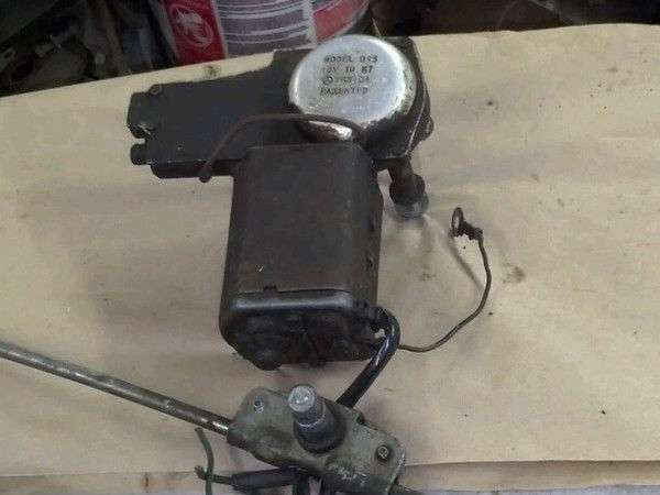
 Note that the wiper motor (photo right) has a black grounding wire that may be grounded to the chassis near the motor. But for the MGA there is a Black ground wire in the harness running to the motor, so it does not have to be locally grounded. There is also a Green wire in the harness to bring power to the motor, as well as one Black/Green wire that is switched to ground to make the motor run. For this circuit only one new wire (Black/Orange) is added between the switch and motor to provide the signal for high speed running. All other new wiring for the relays is to be done at, on, or very near to the motor. You may consider the relays to be part of the motor, possibly attached to the motor or the motor mounting plate. Note that the wiper motor (photo right) has a black grounding wire that may be grounded to the chassis near the motor. But for the MGA there is a Black ground wire in the harness running to the motor, so it does not have to be locally grounded. There is also a Green wire in the harness to bring power to the motor, as well as one Black/Green wire that is switched to ground to make the motor run. For this circuit only one new wire (Black/Orange) is added between the switch and motor to provide the signal for high speed running. All other new wiring for the relays is to be done at, on, or very near to the motor. You may consider the relays to be part of the motor, possibly attached to the motor or the motor mounting plate.
Click to show wiring diagram in separate window for printing.
See article ET-219D on prior page for DR3 2-speed wiper motor function.
Remember that this motor parks by running backward to actuate a special cam that changes length of the drive cable. The diagram above shows the circuit "at rest" in the parked condition with the Park Switch open. No ground connection means it is not running. But it was last running in the reverse direction to get to this position. Reversing direction of rotation of the motor is done by reversing polarity of the field coil (swapping two wires on the field coil).
Pulling the dash switch to first position grounds the Black/Green wire (as original in the MGA). This switches the first relay (R1) to swap connections on the field coil (White and Brown wires) to make the motor run in the forward direction. It also grounds the Red wire in the motor to "override" the park switch to get the motor started. When running (forward) the cam in the motor changes length of the drive cable such that the Park switch is never touched and remains closed at all times. The circuit then has two paths to ground, through the dash switch and through the Park switch. The motor is then running in "Normal" speed.
Pulling the dash switch to second position grounds the Black/Orange wire. This switches the second relay (R2) to change the motor Field ground connection to opposite end of the Resistor, putting the resistor in series with the Field winding. Reduced current in the field coil makes the motor run faster (with reduced torque) for "High" speed. Pushing the dash switch to first position drops out the second relay, bypassing the resistor to put the motor back into "Normal" speed.
Pushing the dash switch back to rest position breaks the controlling ground connections. This drops out both relays, reverting to the circuit shown above. That switches the motor back to "Normal" speed (R2) as well as swapping the field coil polarity (R1) to make the motor run backward until the park switch will break the circuit to stop the motor in the park position. The last trick here is the diode on the side of relay R1. This allows the manual switch to ground the motor to make it start, but does not allow the park switch to trigger the relay coil (which would prevent it from switching back to reverse direction).
Orientation of the diode depends on electrical system polarity, positive or negative earth. The diode must carry full current of the motor (about 4 amps) to get it started (after which the park switch can share the load while running).
I'm considering another trick. The motor might have about 3 ohms resistance to draw about 4-amps current. Suppose we add a low value resistor in series with the Black/Green wire, not more than 10% of the motor resistance (so it doesn't prevent the motor from starting), maybe 1/4 ohm or there about. This should drop voltage by 1 volt or so at the bottom end of the diode. Once the motor is running the park switch will be closed, applying full voltage to the top end of the diode (and full system voltage to keep the motor running). Higher voltage at top end of the diode wants to back drive current, but the diode would prevent that, resulting in all motor current going through the park switch (and the control switch only carrying current to trigger the relays). Relay trigger coil resistance is much higher, maybe 60 ohms or so. Once running with no current through the diode, voltage at the Black/Green wire (and its series resistor) would be very close to system voltage but still slightly lower than above the diode, so still no current flowing through the diode.
I'm still looking at this to see if I can figure out how to do it without the diode, but also do not want to add another relay. The floor is open to comment and suggestions.
|