The MGA With An Attitude
FOUR WAY FLASHERS, MGA 1600 with Switch - ET-244A
This article is for the MGA 1600, or later production vehicles where the front and rear turn signal lamps are wired together without a relay. It involves a direct acting switch that will not work with the 1500 type circuit that uses the brake lamp bulbs for rear turn signals.
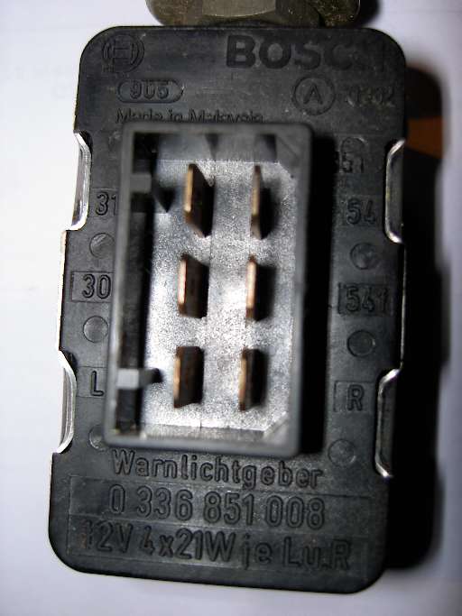
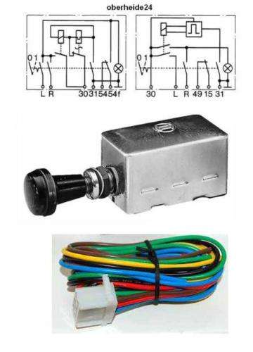
Here are two slightly different electrical diagrams for the internal arrangement of this switch. I suppose they are different models, but once you figure it out they are functionally identical (not looking inside the box). Terminals 30 and 31 are power input and ground. L and R get connected to the left and right turn signal lamps (at back of the turn signal switch). There is also a normally closed contact between terminals 49 and 15 (or 54 and 54f).
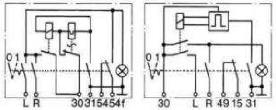
Manually pulling switch to "ON" position, opens the NC contact and connects L and R together. It also grounds the internal flasher unit so it will begin to sequence. The flasher unit alternately makes and breaks the power circuit to the lamps to affect flashing. The NC contact could be connected in series with the wire between the original flasher unit and the Turn Signal switch. If the TS switch might be switched on at the same time as the 4-way switch, this disconnect contact will prevent the two flasher units from fighting each other. That is, turn signals will not work when the 4-way is operating.
|