The MGA With An Attitude
MECHANICAL TIMING TURN SIGNAL SWITCH - TS-102
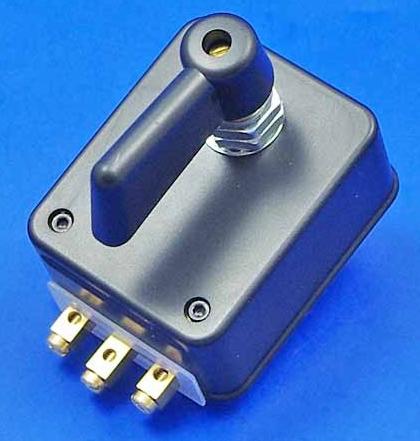
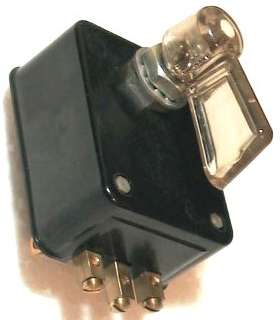
Shown below is an aftermarket mechanical timing turn signal switch which has been periodically showing up on eBay. The description comes from a recent purchaser.
Bill Joy <WMJOY@aol.com> wrote:
----------
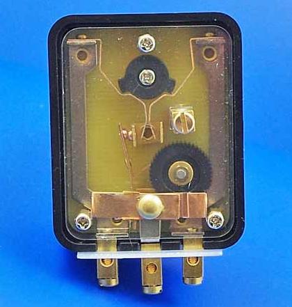
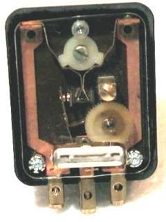
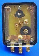
".... It came in a plain cardboard box, with no markings on it except the hand written notation 'FT-35'. The case is black Bakelite with no markings. The back, which looked open on e-bay, is actually covered with a clear plastic flat piece, held in place by three fasteners, which remains open around the edge. The three brass terminals on the bottom are marked on the clear plastic from left to right "G" "+" and "D". Another brass terminal located right center is not identified or marked.
I am fairly sure the one I got was the second one sold on e-bay by the same seller. How they ended up in Cyprus is beyond me.
The center post at the bottom is the positive terminal. The white bar that appears to cross all three terminals actually sits proud of the signal and is a replaceable fuse for the positive terminal. It is made of some clay material with a metal strip fitted into a depression across its surface. It spring fits into its holder. The center post carries current to the metal bar that angles up from the center of the bottom. It has an arm that contacts the
The left and right posts run up either side of the signal box and attach to spring metal that contacts the white wheel at the top center with the two pips on it. The spring metal then comes together in the center of the U shaped metal bar.
The screw you see just right of the U shaped metal bar is actually the top of a fourth post that stands proud of the switch about as far out as the fuse.
All that you see under the clear plastic covering is about half the deep of the entire depth of the switch. The fourth post doesn't contact any of the other elements you can see from the back. It goes through the back and must make contact inside the switch. The plastic covering is held in place with two silver fasteners you can see at the bottom and one in the center of the top, which looks smaller because it has lost part of its fastening.
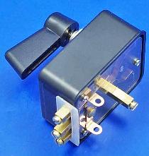
When you turn the clear plastic lever on the face of the signal you hear a clicking sound and it appears that a spring is being wound. The white wheel at the top turns the same direction as the lever and the pip presses the spring metal into contact with the side of the U shaped metal bar. This closes the circuit. However, it doesn't remain closed. Regardless of which way your turn the lever, after you release the lever, the white tooth gear begins turning clockwise. The teeth forces the metal bar that is attached to the positive post to break contact with the U shaped metal bar. It appears to be a mechanical way to cause the turn signal to flash when it is activated. Although the gear turns for about 23 seconds, the pip on the wheel returns to rest after about 17 seconds, so the signal is active for 17 seconds.
Concerning that fourth post in the center of the switch, my little multimeter shows no continuity from it to the positive post, but does show it from the left post when the lever goes left and from the right post when the lever goes right. I would think that would run a constant dash light activating when either turning right or left.
So, if it fits behind the dash it could be used as a turn signal for an MGA, but the electric flasher unit would probably have to be bypassed. Hope this description is understandable and isn't too long."
----------
Now here is where I have a little fun with speculation and unanswered questions.
Apparently there are no instructions or description packed with the switch, not even a rudimentary wiring diagram. The terminal in center of the back plate is apparently an auxillary terminal for the dash indicator lamp. This should not be required for use on the MGA. The timing device is apparently a mechanical clock drive with a main spring being wound up by operation of the manual lever. This clock drive would be hidden within the switch housing ahead of the parts which are visible from the back. Since the assembly is riveted together, until such time as someone might take one of these switches apart for internal inspection, I can only presume that there are no owner serviceable parts inside. As such, if you use this switch, you might want to stock some sort of replacement part in case it fails.
I am patiently waiting for further report. Someone should wire this switch up to a pair of 21 watt bulbs (in parallel on a single output terminal) and a battery for a test to see how it works under electrical load. I would like to know if the internal mechanism would actually break the circuit intermittently while running to provide the flashing. If the switch itself does not do the flashing function, then the external flasher unit is still required. The idea that this switch might actually do the flashing function internally is an interresting concept, as it might then be a complete stand alone turn signal package. I'm guessing that it does not, but I could be wrong. If the switch itself flashes, then it would not work on the MGA 1500 cars, but it could work on the 1600's. The 1600 cars have independent turn signal bulbs front an rear, always connected together. For those cars the flasher unit supplies power to the switch. If the switch does the flashing it would still work without the flasher init. The 1500 cars use a common rear bulb for both brake light and turn signal. There is a complex relay box that takes that lamp out of the brake light circuit and connects it to the front lamp when activating the turn signal. For that setup the flasher unit supplies power to an input terminal on the relay box. The switch then must have constant power to operate the relay coils in the relay box. If the switch flashes it will not work for this setup. If the switch does not flash, then it can be a direct swap in place of the original vacuum delay switch, and you just don't connect the 4th terminal. If it does flash, I would be hard pressed to explain how it could work for the MGA 1500 circuits.
I think it is not a good thing if this switch acts differently from the original switch. Otherwise a new driver who knows MGAs well might be baffled by the strange operation. It could be a safety hazzard if the signals don't work in the "normal" fashion.
Then there remains the question of long term reliability. I still use my original 45 year old vacuum operated switch. It has needed some maintenance and adjustment over the decades, but has all indications of otherwise lasting (or being repairable) forever. This new mechanical delay switch might turn out to be like electronic ignition, nice and stable as long as it works, but may not last as long. I find it easy enough to live with the quirks of the original well known devices. I'm a little skeptical about long term use of a device with no known track record. What might happen to it after a number of years of regular use? Or what might happen to it if it was left in damp storage for a few years, the same way the cars are often neglected? Some of these answers might be easier if this device had a prior usage history, like if it was original equipment on some commonly known car model produced 20 to 50 years ago. So I'm still curious if it's an old design or something relatively new.
Here are some sources for this part:
Complete Automobilist -
Vintage Motor Spares
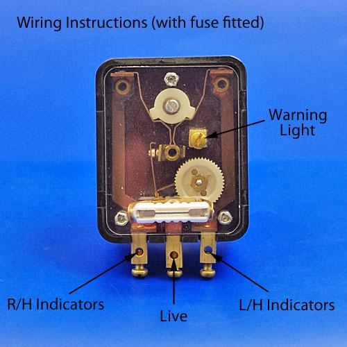
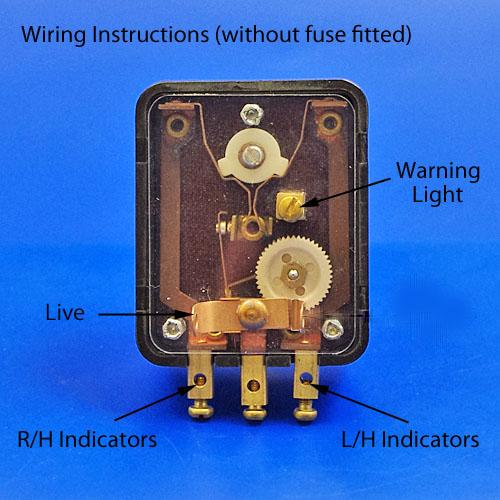
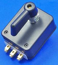
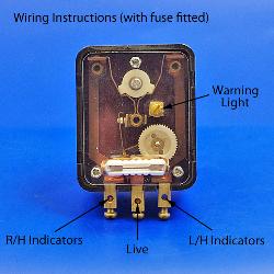
More pictures from Complete Automobilist, this one without the fuse:

|