The MGA With An Attitude
ENGINE REMOVAL Lifting Methods - BE-106
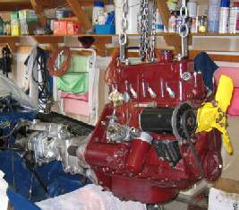
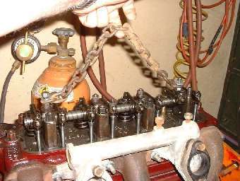 Everyone seems to have their own method for lifting an engine. Some may work better than others depending on your tools or facilities at hand. The prior page shows my favorite solution, originally devised decades ago when I was on a tight budget, it still works well for me today. It is just a short length of 1/4-inch chain (about 16 inches long) attached to the valve cover studs with flat washers and hex nuts screwed up tight, and whatever type of hoist you may have handy. Position the hook fore or aft on the chain depending on best point of balance, lift the engine, and roll the car our from underneath (if the hoist does not move). Our good friend John Twist of University Motors also uses this method. If you are so inclined you can use the same technique to lift the cylinder head off the engine, after removing the eleven (11) larger head nuts.
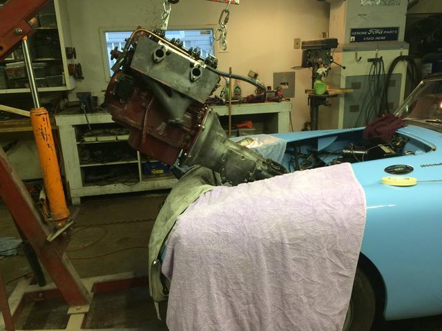
It is most convenient to be able to tilt the engine a little fore/aft when aligning the engine to gearbox. To that end, for the method above you can move the hook fore/aft on the chain (before taking up the weight) to get the natural free tilt angle as you like. Then it will tilt a little in any direction with a bit of a hand nudge as it hangs on the hook. The angle of dangle depends on the center of gravity, which in turn depends on what you have attached to the engine. With no flywheel it hangs level with hook near center of the chain. With flywheel and clutch attached it will hang with tail down a little, unless you move the hook back about one chain link. With gearbox attached the hook needs to go a couple links farther back, depending on how much tilt you need.
 If the gearbox is installed in the car first, then the engine to follow, the engine only needs a small tilt back to align with the gearbox on final approach. If the engine and gearbox are to be installed as one assembly, then the whole thing needs a rather radical tip with tail down to get into the engine bay. I find it easier to do engine separate so it doesn't need to be tilted so far.
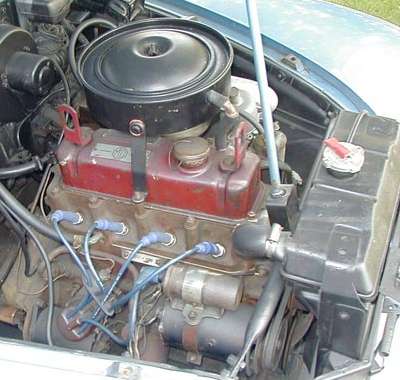
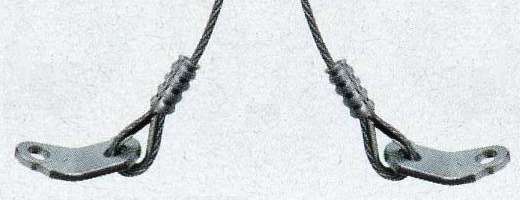
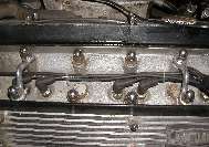
Pictures below show a factory style lifting bracket that may have been original equipment for the MG ZB Magnette, but was an optional accessory for the MGA (because it doesn't fit under the bonnet on the MGA). Notice item 13 in the illustration is a thick flat washer (spacer). This assembly calls for the use of the washer or the lifting bracket, but not both at the same time. The spacer is the same thickness as the bracket and should be removed when the bracket is installed. This setup allows lifting of the engine with the valve cover in place. These brackets are sometimes attached to the head bolts at front and rear of the head, in which case they may be left in place and do fit under the bonnet on the MGA.
 Picture at right shows similar lifting brackets being an integral part of a chain(s) that may be part of an additional lift and leveling device. Notice also the gearbox attached to the engine. This requires the load to be taken up closer to the rear lifting point to keep the assembly near level.
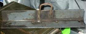
Picture above left shows and angle iron fixture with two holes in the bottom leg to attach to the valve cover studs, and a U-bolt welded in the center for the hook. Advantage of this part is better bracing and less bending load on the rocker studs. Disadvantage is the fixed hook point that limits control of tilt angle. Alternative to the fixed U-bolt is to drill two holes near the top edge of the angle iron and attach a short chain similar to the one shown at top of page. This would allow repositioning of the hook for best balance and tilt.

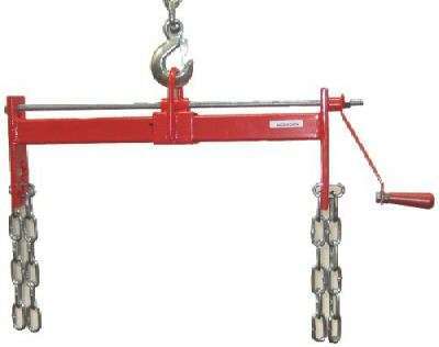
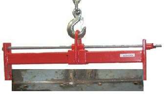
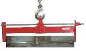
Picture at right shows a commercially available fixture that enables fore/aft adjustment of the hook point under load. This allows you to change the tilt angle at any time by simple winding of the crank handle. This can be very handy for installing engine and gearbox together when it needs high tilt to enter the engine bay and lower tilt for final seating on the engine mounts. Disadvantage is that the more gadgets you put between the hook and engine the higher the hoist has to lift.
 A friend of mine has a variation on these last two techniques. He uses an angle iron bracket like above left (but somewhat smaller) attached directly to the bottom of the screw-tilt fixture (close coupled). He also removed the hand crank (for lack of swing space in the car) and welded the hex nut to the lead screw. He then turns the lead screw with a socket on a speed wrench, or sometimes quickly with an air impact driver. I have cobbled together a composite picture at right. This is a nice tilt fixture that does not require much head room.
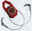
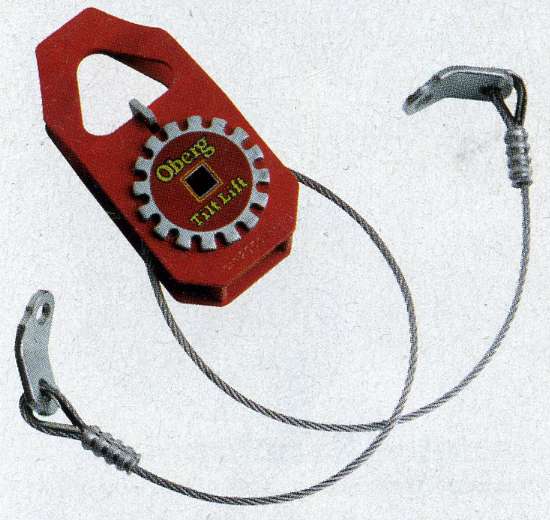
At left is the Oberg TiltLift. It needs a 1/2-inch socket drive to rotate the cable spool, it needs quite a lot of head room, and you may need a ladder to adjust it with the engine lifted high.
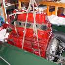
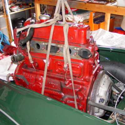
I left the worst for last. In a pinch you can use a rope sling, but you need to be very careful with this one to keep it snug and as short as possible. The real support point with this is at the bottom of the engine. If the engine is allowed to tilt much either forward of backward it could potentially roll right out of the sling with possible nasty consequences.
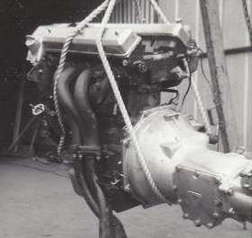
 The Twin Cam engine presents a different problem. In this case it is not a good idea to rig a sling on the angled valve cover studs as they would be pulled sideways at a sharp angle. Photo here shows a rope sling with one loop between engine front plate and oil pan and the other loop around the gearbox.
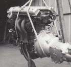
A better solution could be to install lifting loops on the central head studs fore and aft. Picture at left shows a Jaguar engine with this type of lifting bracket. Something similar could be rigged for the MGA Twin Cam engine.

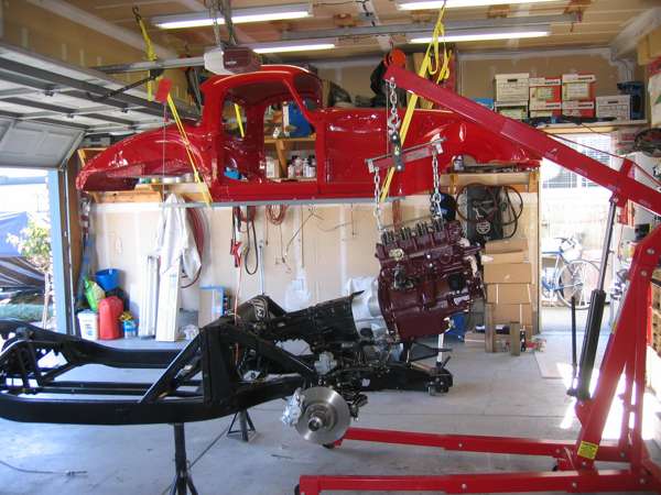
This last picture can give you a good idea how much lift height and head room is required when you use a tilt leveler between the engine and hoist. It will need to go a little higher yet to clear the nose of the car when the body is in place (but not so high if wheels are on the ground).
You should notice in all of the examples using a tilt leveler that the chains hang near vertical at all times, and apply only vertical pull. Any lateral pull on the lifting brackets derives from tilt of the engine and is limited by weight of the engine (and angle of dangle). As mentioned earlier, the nuts securing the brackets should be tight to avoid bending load on the studs. Now one thing you SHOULD NEVER DO is is to use a short length of chain between the brackets with chain at sharp angle and hook in the center. When the chain is pulling at a sharp angle at top end of the bracket, the bracket is pulled hard sideways causing a severe bending load on the stud, in addition to vertical and horizontal loads. That bending type load on the stud is to be avoided to prevent possibly breaking the stud and dropping the engine.
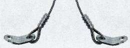 When using lifting brackets with a short length of chain or cable and hook in the middle, bend the long leg of the bracket to be in line with the pull direction of the chain or cable. This will minimize bending load on the stud.
|