The MGA With An Attitude
OIL Pressure Relief and GALLERY PLUGS -- OF-101A
At 05:54 AM 6/19/05 -0500, Stan Wilson wrote:
"The .... engine has several brass plugs that allow access to the oil channels....
 It is a good idea to remove these when rebuilding and flushing the old engine core. However, I can not find a picture, drawing, etc. that shows which holes .... are where located. Also what size should the replacement plugs be?"
This answer got a bit complex, so I took some pictures to markup, and will explain the pressure relief flow cycle in the process. Oil gallery drillings are lettered and plugs are numbered.
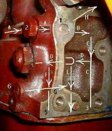
 Starting just above the oil pump, hole A runs from the pump outlet port to the back of the block and is stopped with press fit plug 1 at the back of the block. This hole serves to bring the oil flow to the back corner of the engine block.
Hole B is drilled laterally a few inches toward the center of the block intersecting hole A. This is plugged on the outside with screw plug 2, a male threaded hex head plug sealed with a copper washer. This drilling ducts oil inward to a point just inboard of the position of the relief valve seat.
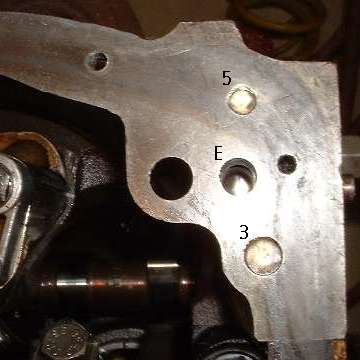
Hole C is drilled upward from the bottom of the block to intersect the inboard end of hole B. This is stopped at the bottom with press fit plug 3. This hole serves to conduct flow downward to the input end of the pressure relief valve.
Hole D is drilled laterally below hole B to intersect hole C. The inboard end of Hole D is relatively small (fat pencil size). This is counter-drilled larger and machined with the tapered seat for the poppet valve and allows a sliding fit for the poppet. The outboard end of the hole is plugged with screw plug 4, a male threaded cap nut which retains the compression spring for the pressure relief poppet. This plug is (originally) sealed with two fiber washers, but one sealing washer will generally work as well. Building up thickness of sealing washers will reduce oil relief pressure slightly (for fine adjustment of relief pressure if desired). Installing shims in the relief valve poppet for the spring height will increase relief pressure.
Hole E is drilled upward from the bottom of the block to intersect hole D immediately outboard of the poppet valve seat. This hole is left open at the bottom to allow the pressure relief bypass oil to return to the sump unrestricted.
Hole F is drilled upward from the bottom of the block to intersect hole D farther outboard, well in back of the poppet, and is plugged at the bottom with press fit plug 5. Hole G is drilled laterally to intersect holes F and E and is stopped at the outside with press fit plug 6. Together holes F and G provide a free flow duct from the back side of the poppet to the sump (hole E). This allows the poppet to move freely out/in with no restriction from behind. The shallow hole in the side of the block near plug 6 is a tooling hole which was used for alignment during original machining of the block.
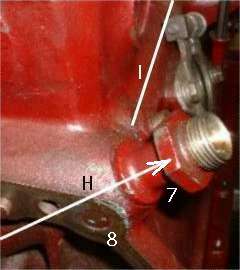 Hole H is drilled parallel to the back of the block but at a falling angle from the right rear corner of the block to intersect hole B. This ultimately sends oil to everything in the engine which gets forced oil flow. This lateral drilling terminates on the right with a very special threaded fitting 7 sealed with a copper washer.
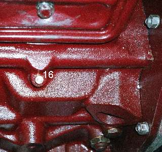
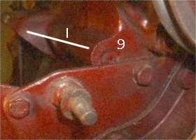 Hole I is drilled the full length of the block front to back (or half way from each end) at the right side of the block intersecting hole H and stopped at both ends with press fit plugs 8 and 9. Plug 9 is visible at the top edge of the engine front plate.
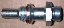
The special fitting 7 has a long nose which extends into the block with a very close fit in hole H so as to be generally sealed around the nose of this fitting. It then accepts full oil flow from hole H to be ducted to the outside while blocking any flow between hole H and hole I. Fitting 7 then also serves as an internal plug between holes H and I. With fitting 7 properly installed, oil exits the block here to pass through external plumbing for the oil cooler (if installed) and through the oil filter assembly to re-enter the block on the right side, flowing into gallery I. If a fitting is used here which does not have this extended internal nose, then oil would pass freely from hole H to hole I and would not pass through the oil cooler or filter.
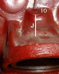
On the right side of the block on top of the oil filter mounting area is a downward angled hole J which is stopped with press fit plug 10. This drilling extends downward to emerge inside the sump just aft of the center web of the block casting and just ahead of the #3 cylinder bore. It also marginally intersects the tapped hole for the oil filter mounting bolt. This drilling serves as a drain to eliminate any possible hydraulic lock when installing the center bolt for the oil filter canister so the bolt can be screwed all the way in with fingers only without resistance.
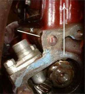

Hole K is drilled the full length of the block front to back (or half way from each end) at the left side of the block (similar to hole I) above the camshaft and below the tappet covers, and stopped at both ends with press fit plugs 11 and 12. There is a small hole in the center camshaft bearing which feeds oil to the gallery K. This gallery then feeds oil to the top of the oil pump drive where hole K marginally intersects the hole (journal) holding the top spigot of the oil pump drive gear.
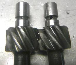
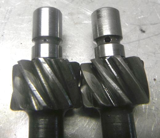
The oil pump drive gear has an axial hole drilled from the top end, and an intersecting radial hole leading to a shallow groove around the bearing spigot. This arrangement brings oil from the low pressure oil gallery into the bearing journal for the oil pump drive gear. Oil escaping from bottom of the journal lubricates the thrust surface of the gear. For the pushrod engines camshaft rotation is clockwise, so the thrust load on the oil pump drive gear is normally downward (except when the engine may turn backward a bit on shutdown). Therefore there is normally no upward thrust load on this gear. For the Twin Cam engines, halfspeed shaft (in the block) rotation is anti-clockwise. Teeth on the oil pump drive gear are then reverse spiral so the oil pump will rotate in correct direction. Thrust load on the Twin Cam oil pump drive gear is normally upward (except when the engine may turn backward a bit on shutdown). The Twin Cam engine then has a thrust washer installed at this location.
In the picture of the gears you may notice the radial holes are different size. That may be a simple manufacturing convenience. Oil flow here is restricted by small radial clearance in the bearing journal, so size of this oil supply hole should not matter. The gear on the right shows considerabe wear on the gear teeth (click for larger picture).
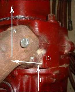
Hole L is drilled down from the top of the block to intersect the rear camshaft bearing journal. This hole feeds oil from the rear cam bearing upward through the head gasket into the cylinder head. In line with hole L in the block is another shallow hole L drilled in the head from the bottom. Hole M is drilled from the back of the head forward about 2 inches (just below the rear exhaust port) intersecting hole L and is stopped at the back with press fit plug 13. Hole N is drilled down from the top of the head (just ahead of the rear exhaust port) to intersect hole M. These holes L, M, and N feed oil into the rear rocker shaft pedestal to lube the rocker assembly.
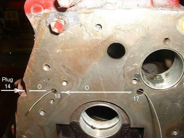
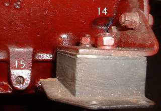 Low on the right side of the block just behind the front plate (engine mount area) is a press fit plug 14. Hard to see in this picture, it is a small flush fit plug within the visible depression. This plug closes a cross drill hole which supplies oil from the front cam bearing to the timing chain tensioner. Item 15 is a slotted screw plug at the sump flange. This is a dipstick port for other engine applications.
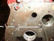
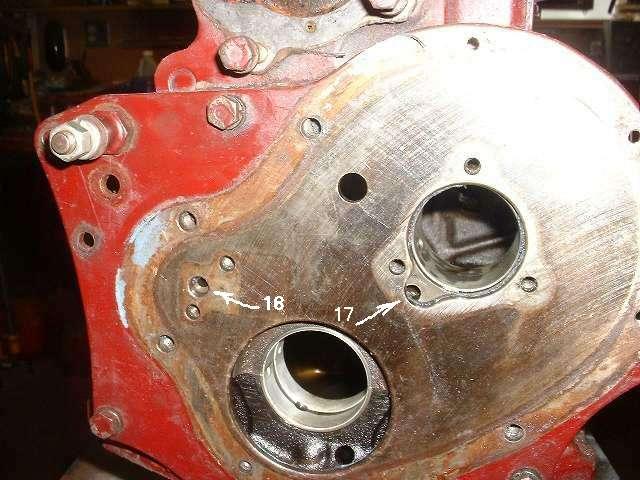
Plug 14 is closing a cross drill hole O. This bore carries oil from the cam thrust plate at the front cam bearing (port 17) to the timing chain tensioner (port 18). Since this hole "O" flow source is oil escaping from the front cam bearing, oil pressure will be reduced and flow will be throttled accordingly. This limited oil flow is going to ultimately supply oil to the rubbing foot on the timing chain tensioner. Along the way there is another flow restrictor orifice at the entrance to the tensioner body.
The late model MGB five main bearing engine has one additional oil plug on the left side directly beneath the rear tappet cover bolt and just below the low pressure oil gallery. This one is positioned at about 45 degree downward angle. The drilling passes through the top end of the space occupied by the gear on the oil pump drive spindle. This passage serves to provide additional oil to the gear on the camshaft, thereby improving lubrication of the gears which drive the oil pump and distributor.
|
|
|