The MGA With An Attitude
How The SYNCHRONIZER Works - GT-110A
The gearbox input shaft (and input gear) drives the laygear any time the input shaft is turning. The laygear (cluster gear) is constantly engaged with some gears on the mainshaft, all different sizes turning at all different speeds. These gears have helical teeth (to run quiet) and always stay in mesh. The mainshaft gear rides on a bushing so it can rotate freely at different speed from the mainshaft. The gear will always turn at different speed from the mainshaft except when the gear is engaged to drive the output.
For the MGA 4-speed 3-synchro gearbox there are two such freewheeling gears on the mainshaft, 2nd and 3rd gears, and these gears will have the synchronizing function. (1st gear is a non-synchronized sliding gear with straight teeth, similar to reverse gear). There is another synchronizer just aft of the input gear that works directly between the input shaft and the output shaft for direct drive 4th gear. Later model MGB 4-synchro units will also have synchronized 1st gear.
On one side of the synchro gear there is a narrow row of small male teeth that will mate with a female spline in the sliding hub. The sliding hub is keyed to the output shaft and can be pushed axially along the mainshaft by the shifting fork, shift rod, and action of the manual shift lever. Pushing the sliding hub into engagement with the side of the gear locks the gear to the output shaft so it can no longer freewheel. The laygear then drives the engaged gear which in turn drives the output shaft while all other gears continue to freewheel. Job of the synchronizer then is to force matching of the speed of the gear to speed of the sliding hub before they will slide together.
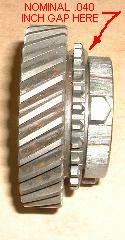

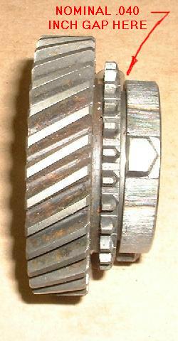
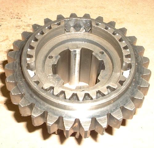
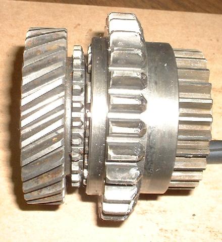
Photo at left, 2nd gear with synchro ring. When pressed together there should be about 0.040-inch space between the mating flat faces. If the cone wears enough for the gap to be .020 or less it would be time to replace the synchro ring. If the "upgrade" steel ring is installed on the original issue gear the flat faces will touch and the synchronizer will not work.
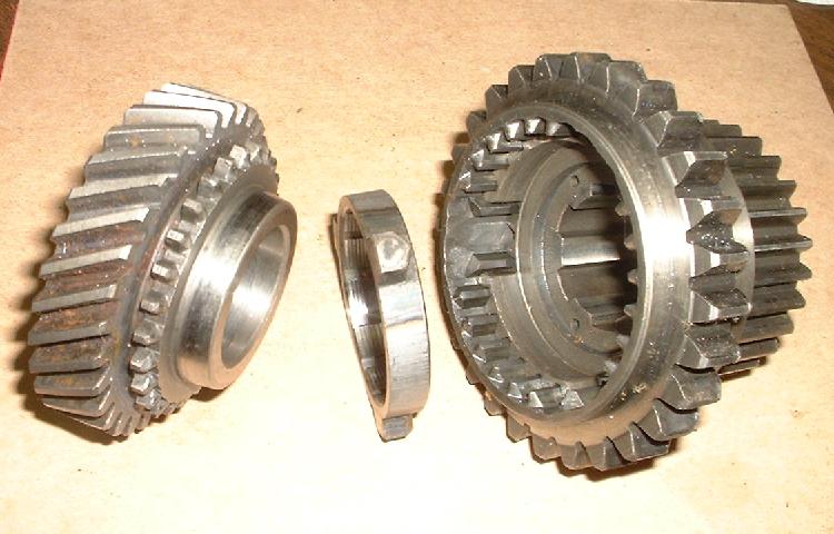
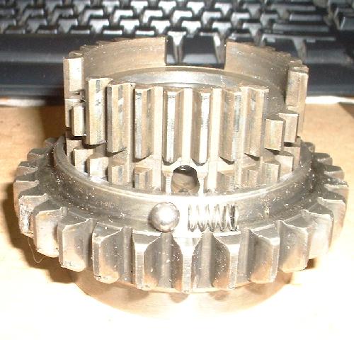
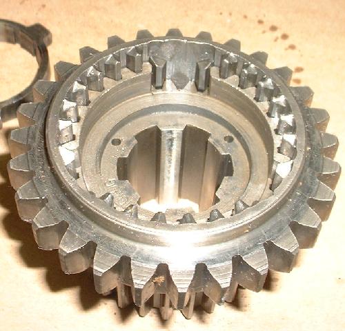
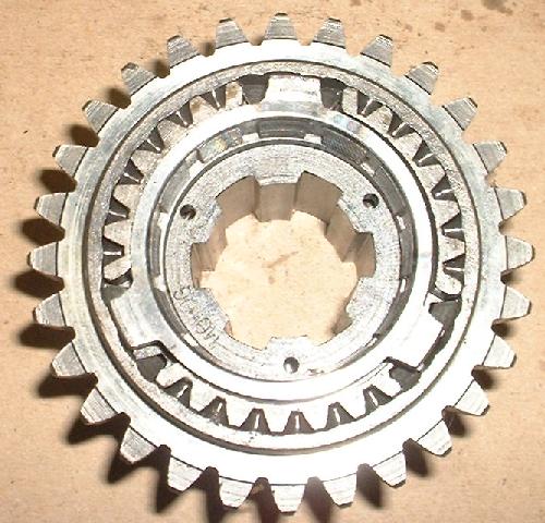
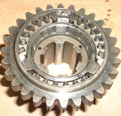
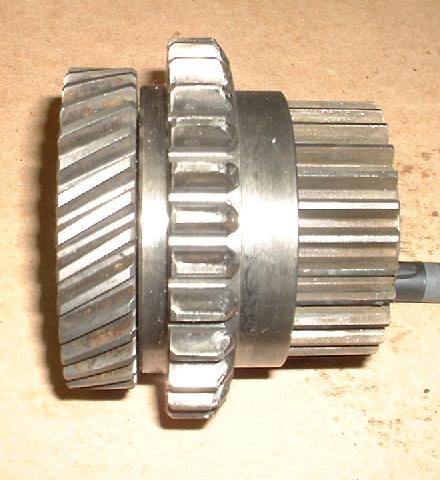
Photo at right: 2nd gear, synchro ring, 1st/2nd sliding hub assembly.
|
What we Yanks call synchronizer ring the Brits calk baulk ring ("baulk" meaning stop or brake, as in friction brake). What happens here is that the baulk ring is actually putting brakes on the rotating gear. When the clutch is depressed the input shaft is free to change speed, so the input either speeds up or slows down to match speed of the output shaft, after which the mating gear and hub can engage.
On the side of the freewheeling gear, after the narrow row of small teeth, there is smooth steel male cone. The synchronizer ring has a mating female cone (the friction brake). The synchro ring also has a few ears on the outer edge that engage with slots in the sliding hub. The synchro ring will then always turn with the sliding hub in harmony with the output shaft. Slots in the sliding hub have a funnel shape at the entrance end where the ring ears reside, and the synchro ring ears have a matching taper on the leading edge. This makes the ear look like a dog house with tapered roof. The entrance slot in the sliding hub is about twice as wide as the ring ear. Beyond the funnel shape the slot in the hub is just wide enough to contain the ring ear like a loose fitting shaft key.
When the gear is rotating at different speed from the ring, and these parts are pressed together, the conical interface serves as a friction brake. The ring is then forced to rotate slightly in relation to the sliding hub. This pushes the ring ears to one side of the wider part of the mating slot in the hub. The ring ears then being misaligned from the narrower slot will prevent the sliding hub from moving forward to engage the teeth on the side of the gear. The taper of the doghouse ear wants to slide down the taper in the funnel slot, but torque caused by friction of the cone brake is high enough to hold the ring ear misaligned to one side of the wider slot.
As long as the gear is rotating at different speed from the hub, the harder you push the more friction results in the cone brake to hold the ring ears misaligned, so there is no way to force the sliding hub to move forward, no matter how much force you apply. Assuming the clutch is disengaged so the input shaft can change speed, braking friction in the cone will eventually reduce the speed difference between the gear and the sliding hub. Once the gear has been slowed down (or sped up) to match rotational speed of the sliding hub, torque on the synchro ring brake cone suddenly disappears. The ring ears are then free to slide down the funnel and drop into the narrower part of the slot in the sliding hub. The sliding hub can then move forward to engage splines to the side of the gear, locking the gear to the output shaft. Your gear selection is then finished, so let the clutch up, hit the throttle and go.
You may spend a minute to think about which rotating parts have to speed up or slow down while shifting. Say you get up to 40 mph in 2nd gear (about 5000 rpm) and want to shift into 3rd (about 3200 rpm). Get off throttle, press clutch, shift about as quickly as you like, release clutch and get back on throttle. When you move the shifter from 2nd to neutral, not much happens as moving parts tend to keep moving due to inertia. However, in the time it takes you to move the shifter from neutral to 3rd the gearbox input shaft and clutch disk have to slow down from 5000 rpm to 3200 rpm. It does that in a fraction of a second,perhaps 1/2 second with a gentle shift or 1/10 second with fast forceful shift. The clutch disc alone has considerable mass to change speed that quickly, so the baulk ring is going to dissipate a lot of energy in a very short period of time. That lost energy will be turned into heat, same as what happens with brakes at the wheels when you slow the car quickly. This is why the synchronizer ring is called "baulk ring" (or brake ring).
There are a number of things that affect the function of the synchronizer. The most important design feature is the angle of the cone. A more acute angle increases braking friction, but if the angle is too acute it will cause the mating cone parts to lock together and never release. Viscosity and slipperiness of the lubricating oil will also affect friction on the cone brake. If oil is more slippery it needs a more acute cone angle. As such, certain kinds of very slippery synthetic oil may reduce friction enough to impair function of the synchronizer. Material of the baulk ring also affects friction. Changing the ring material from brass to steel may require a different cone angle to produce the same braking torque. This is why the brass and steel rings intentionally have different dimensions so they cannot be physically swapped. To use the steel ring you have to also install the appropriate mating gear (with different cone dimensions).
|