The MGA With An Attitude
LAYSHAFT IMPROVEMENTS for the MGA Gearbox - GT-204

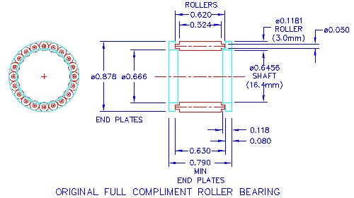
 This was a bit of a surprise the first time I saw it. The original needle bearings for the layshaft consisted of
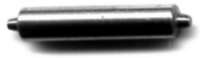
 two end plates and 20 loose rollers for each of the three bearings. The rollers have cylindrical pin ends. The side plates have an "L" shape for cross section providing a small flange around the ID on one side to catch the needle tips. Drop one side plate down the bore of the laygear. Insert the shaft where the side plate will hold it centered and the end of the shaft is near the end of the bore. Then drop in 20 individual needle rollers followed by the second side plate, after which you can remove the shaft and install a snap ring or the tube spacer, and the rollers will be held in place without the shaft. With the tube spacer and four snap rings you would have to load 71 loose pieces inside the laygear to assemble the needle bearings.
Now before you go singing the praises for modern cartridge bearings, consider that there is a functional advantage to this loose assembly configuration. Using loose rollers with no cage allows installation of a full compliment of 20 load bearing rollers around the shaft with just enough space between the rollers for oil film. This lets about 8 rollers carry the load in one direction (40% of the circle), and maybe 6 rollers will carry the bulk of the load while the ones on the sides don't hold much.
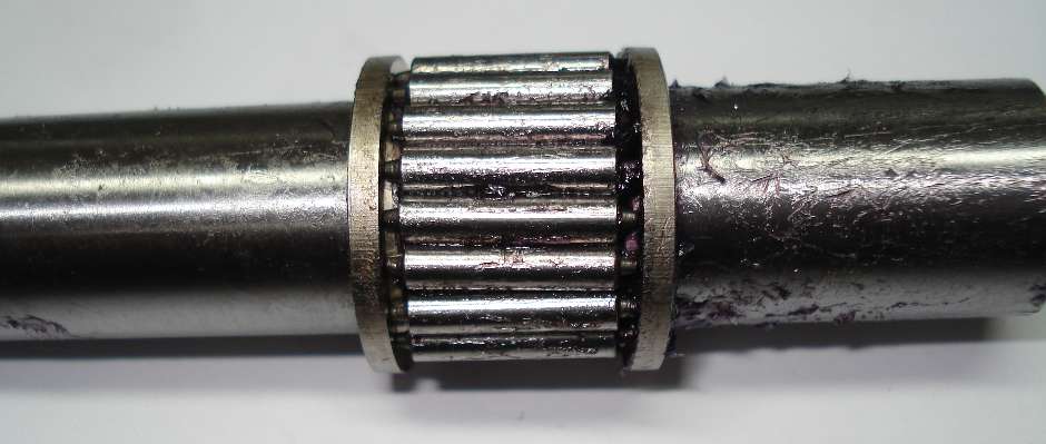
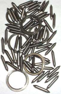
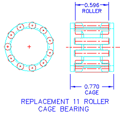
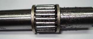
Pre-assembled cage bearings require some space between the rollers for the cage webs. In that case there may only be space enough left for perhaps 16 rollers (or less), and the load ends up bearing on fewer rollers on one side of the shaft. The picture at right shows an original needle bearing with 20 loose rollers assembled on a layshaft and held together with grease. Beside it is a replacement cartridge bearing with only 11 rollers (gasp) in a cage. Result is having maybe 4 rollers carrying the bulk of the load instead of 8, which can make a HUGE difference in the wear life of the shaft.
Addendum June 2005:
At 11:31 PM 6/29/05 -0600, Fletcher Millmore wrote:
I spent a good part of the last 40 years as a Brit car mechanic, done a zillion gearboxes. Regarding the loose needle laygear bearings, these came assembled in a tin "outer race". After putting required circlips, spacer, etc in, you just put the lot over the layshaft, and pushed the whole works out of the temp "race", and into the gear. Then a circlip to hold it all in. No fiddling at all!
The theory of the caged needles is that loose ones get out of line with the shaft, resulting in end contact with the outer race, and center contact with the shaft, thus breaking the needles. As well, there is some problem with friction between adjacent needles, where the contacting surfaces are going in opposite directions, and lack of lubrication between them - mainly a problem on very high speed applications. I have observed these problems, especially noticeable on longer needle applications - the outer race will show wear at the ends of the needle, and the shaft at the center; and yes indeed, sometimes the needles are broken in half but you have to take it apart at just the right time - disaster do come quick! You can sometimes see it on the 1st-3rd motion shaft spigot needles. The use of two short bearings instead of one long is to deal with this problem.
All that said, in this application I tend to agree that since the shaft surface failure seems definitely to be the problem, more rollers in contact is better. A better shaft might have helped too! When the change to caged rollers started, we used to get some that had 3 rollers, then a cage bar, then 3 rollers, etc. That seemed to be a good compromise. Thought you might find this of interest, Fletcher
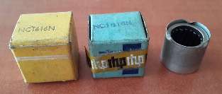
Found a few pieces of OEM bearings.

Ramsome Hoffman Pollard Limited (RHP) -- MADE IN ENGLAND
RHP part number NC1616 -- BL part number: 3H2865
Shaft dia: 16.4-mm (0.6455-in) -- Roller dia: 3.0-mm (0.1181-in)
Outside dia: 22.420-mm (.8827-in) -- Width: 20.0-mm (0.7874-in)
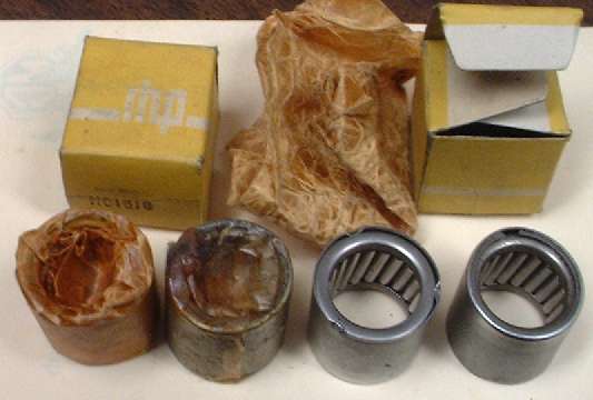
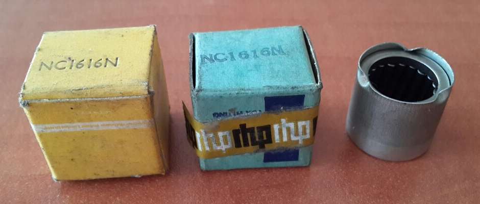
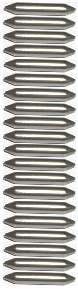
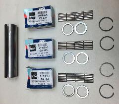
Here is a picture of the way full compliment needle bearings are packaged and shipped prior to installation. Opening the box you find the bearings wrapped in oiled paper (far left) or waxed paper (second from left) to preserve them in storage. The assembly is contained in a thin metal cup with a narrow flange at one end (far right). The parts are retained in the cup buy a few small crimps in the edge of the cup on the other end (second from right). Notice with the bearing on far right there is a snap ring included inside the cup.
For assembly one snap ring and the bearing spacer tube are installed in the gear, and a layshaft (or dummy shaft) is placed inside. The bearing with the tin cup is placed over the shaft and positioned against the end of the gear. A thin wall tube "punch" is then used to push the bearing assembly out of the cup and into the gear, pushing the snap ring along with it until the ring snaps into place in the bore. Repeat for additional bearings. Once the bearings and snap rings are in place the shaft can be removed, as the needle rollers are held in place by the internally flanged bearing end plates (same as in the picture above).
One curiosity comes to mind here. When installing bearings and snap rings at the inboard positions, how do you get the snap ring to go past the first groove without being caught there? I suppose the solution is to use a pusher punch with a slightly angled end so the ring goes in with a little slope on it until it goes past the first groove. Then change to a flat nose punch to push it the rest of the way until it snaps into the second groove.
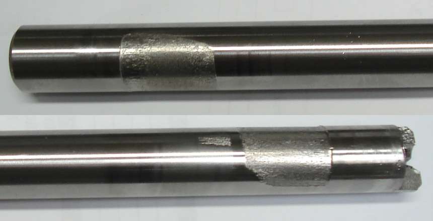
One of the high wear points of the MGA gearbox is the layshaft in the area of the single rear needle bearing. There are a few ways to improve upon this.
 I will take the easiest modification first. You can measure the length of one of the needle bearings (0.770 inch), then cut the tube spacer shorter by that amount, and install a 4th bearing to share the load at the back end of the laygear. The layshaft bearings are oiled through radial drill holes from a center bore in the shaft. It is not absolutely necessary, but probably a good idea to drill the fourth radial hole to supply oil to the new bearing, in which case you also need to extend depth of the center drilling from the end of the shaft.
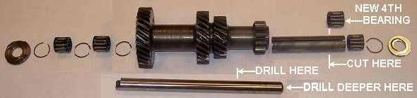
The shaft is good quality steel and should be case hardened. Core hardness (through hardening) should be low enough to drill with a good high speed steel drill bit. Case hardening should be about 60-Rc, hard enough so it cannot be scratched with a file. For this consider buying a "cobalt" drill bit. Set it up in a drill press and use a slow feed with a steady hand so the drill bit won't catch and break at the moment that it runs through into the center hole. If you break the bit you will likely have to take the layshaft to a shop with an EDM machine to have the broken bit burned out. Finish by deburring the new radial hole, and reassemble the gearbox in normal manner but with four needle bearings rather than three (shortening the tube spacer accordingly).
There may be one additional problem. The last time I did this I discovered that the bore hole in the laygear was not finished all the way through. Apparently it was finish ground or lapped to final bore size by reaching in from opposite ends, and it may not be finished to full diameter all the way through the center. When I slipped the additional needle bearing in from the back end of the laygear the shaft could not be passed through the bearing. When I installed the shaft first, then slid the bearing into place, the bearing would not go all the way in to the desired final position, but stopped almost 1/4 inch short. There appeared to be a very small step in the bore at that point. My solution was to carefully measure the depth of bore for the location of the step, then use a brake cylinder hone to enlarge the bore to correct working size just beyond this step.
There is another slightly strange way to install a full compliment of loose needle rollers. By coincidence the spigot bearing between the input gear and nose of the output shaft has the same needle roller diameter, but longer rollers, and only 18 rollers rather than 20. The rollers are a nominal 3 mm diameter (0.1181"). Tolerance should be -.0001 -.0003, making the size range .1180" to .1178". These rollers are longer than the layshaft needle bearings, but the layshaft spacer tube may be cut shorter to accommodate use of the spigot bearing rollers in the layshaft assembly. Do be sure to use 20 rollers. For this modification see article GT-204D.
The lay gear itself does not have any significant problem with bearing wear. It is a very tough forging, it has more bearing surface area than the shaft, and it is always rotating relative to the load so any bearing wear is equally distributed all the way around the bore. The shaft on the other hand is smaller and is stationary with the load always in one direction, so it wears badly on one side.
Adding the second bearing in the small end of the gear effectively doubles the load bearing area on the shaft, while at the same time cutting the spot loading in half. In theory this should make the shaft life more than twice as long (perhaps up to four times as long). The original style single bearing with full compliment of rollers might last 100,000 miles, maybe a little more with luck. The cage bearing has fewer rollers to carry the load and much higher spot loading, so the shaft wears much faster. It has been my experience that this setup will only run about 60,000 miles before the layshaft is shot. Installing the second bearing may extend that back up to 100,000 miles, so you may never need to fix it again, depending on how much you intend to drive the car. Two full compliment bearings at each end would be even better yet.
I drive the MG a lot so longer layshaft life means a lot to me. This point comes home pretty strong when it dawns on you that you may have already gone through two or three rebuilt gearboxes and you're about to do it again because of the worn layshaft.
The second possible modification is to install the larger diameter layshaft with matching 4-bearing set and laygear from the late production 3-synchronizer MGB gearbox. These units were produced starting with MGB engine number GB74720 (STD) or GB74529 (OD) during the 1967 production model year (ending October 1967). The trick to this is that you have to ream the layshaft mounting holes in the main gear case from 0.645" dia to 0.668" diameter. Some sage advice on this procedure comes from Mark Palmer on the MGA Twin Cam group list as follows.
"You need to take care to make sure the holes remain in line. The best, and easiest, way to do this is to use a piloted, adjustable reamer. It pilots in one hole while it cuts the other, to keep things in line. And it's adjustable (over a small range) to give the proper clearance.
Automotive machine shops don't have such tools, and neither do most general-purpose machine shops. You can get some pretty sloppy holes if someone doesn't know what they're doing or doesn't have the right tool. You can also get some extremely high price quotes by shops that propose to do the work with other methods.
The place to go is an electric motor rebuilding shop. They have exactly the right type of reamer, usually called an "end bell reamer" -- used for reaming the holes in the end bells of electric motors. Take the gear case and the new, larger diameter shaft, and they will adjust their reamer to give a good fit.
Just about any decent sized city will have a professional electric motor shop, so it's easy to find -- once you know what you're looking for.
Or, you can become a local hero (to a very small group of MG people) and buy the reamer and do the job for yourself and your friends. Reamer is certain to last a lifetime!"
If you are going to the bother and expense to do these things, you might also consider installing the up rated 2nd gear steel synchronizer ring and matching 2nd gear (together being multiple times the cost of an original brass synchro ring).
The third possible modification is to install most of the MGB gearbox from that same period, including the larger layshaft and associated parts. You can install the MGA 1600 type gearbox rear housing on the 3-synchro MGB gearbox to have the original type MGA gearbox mount and remote shift mechanism. You may also install the MGA input shaft (and gear) to have matching parts for the MGA clutch disk (10 or 23 spline) and spigot bearing. If you use the MGB input shaft (and matching clutch disk) you may need to machine down the front end of the shaft to fit the spigot bearing in the MGA crankshaft. That becomes the opposite proposition if you also install an MGB engine with larger spigot bearing, in which case you can use the MGB input shaft (and clutch disk) to match. Or use the MGA input shaft and a reducing adapter bushing for the MGB spigot bearing.
The MGB gear case will have the high starter mount position similar to the MGA 1600 type gearbox. This implies that for the MGA 1500 car you would need to make the tunnel modifications the same as installing a 1600 gearbox in the 1500 car (including a different propshaft). Considering the work involved there, for the 1500 car it may be easier to revert to option two and ream the original 1500 type gearcase to accept the larger MGB layshaft and laygear (from 1967).
The fourth possible modification would be to install a complete 4-synchronizer MGB gearbox (1968 model or later). This is a considerably larger project as it requires substantial modification to the MGA tunnel AND FRAME to accommodate the larger gearbox. See more notes on gearbox swaps in separate article Installing various MGB gearboxes into the MGA.
Addendum January 14, 2014:
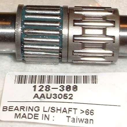
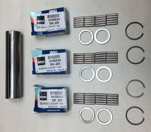
I just received a message from Michael Pratt, Moss Motors UK. They are still searching for manufacturer who can make the original full compliment bearings (3H2865) for the layshaft. HOWEVER, .... meanwhile they have found and procured a substantial quantity of New Old Stock original bearings which they are now selling. They are NC1616N from RHP and R&M. (The N stands for use with snap ring).
www.moss-europe.co.uk/shop-by-model/mg/mga/clutch-gearbox-axle/gearboxes-components
Addendum, Jan 22, 2015:
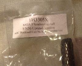
After a few fits and starts, a couple of rejects and re-manufacture, Moss Motors UK now has new layshafts advertised as 60-62 HRC. You must order part number 1H3305X, as the softer shafts are still being sold under the original part number 1H3305. Hopefully these will be available soon from Moss Motors USA.
Addendum, March 12, 2022:
Apparently inventory of NOS style bearing kits has been sold out, and Moss Motors now has new reproduction bearing kits available. The new parts are different in that they use plain flat end rollers and flat sided thrust washers, so there are now new assembly instructions noting to use grease to hold the needle rollers in place during assembly.
www.moss-europe.co.uk/shop-by-model/mg/mga/clutch-gearbox-axle/gearboxes-components
|