The MGA With An Attitude
These notes are provided by David Adams in the UK. You may contact him with questions at davidandpammy@btinternet.com Fitting a HiGear Conversion for a Ford Type 9 Gearbox to an MGB 18V Engine in an MGA
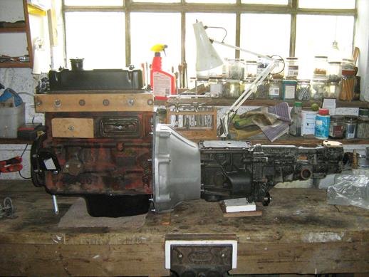
Having cut the extension housing off the front of the gearbox as instructed, I did a trial fit of the new bell housing to the front cover of the T9 gearbox. The gearbox front cover flange did not want to enter the counterbore in the rear of the bell housing. The flange would start and then rocked on a couple of high points which were eased off with a bearing scraper and progressing like that the flange entered fully. Working on through the instructions, the existing gearbox extension bronze bush in the end of the crankshaft had to be removed and Peter suggested sawing it through with a broken hacksaw blade in two places so it could fall out, which it did. 
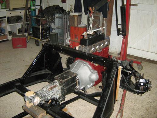
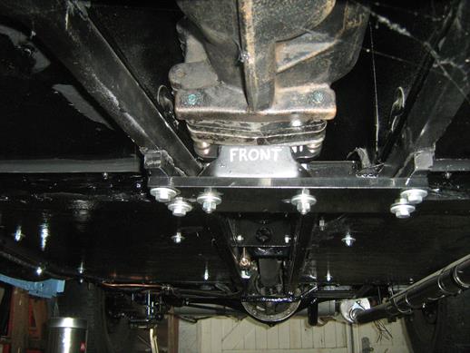
 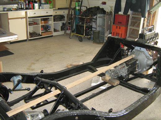 I did a trial fit of the engine and gearbox and used a straightedge to align the gearbox with the diff top bolt, assembled the gearbox rear mounting and marked out the bolt holes to be drilled in the chassis channels. I also noted which way round the backplate to bell housing bolts should be entered for future removal, exhaust pipe brackets and so on. 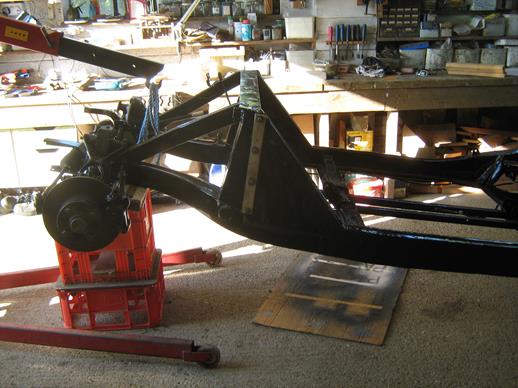 Then I removed the engine and gearbox and lifted the front of the chassis onto a support to allow space for drilling the channels. After painting the engine, the chassis was lowered, the engine and gearbox inserted and bolted up. 
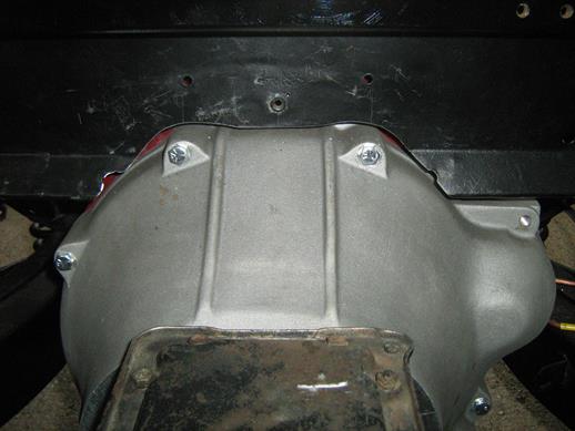
 A trial fit of the toe board showed that there would have to be some alteration and cutting to clear the bell housing. The pencil marks in the second picture below show the location of the toe board. I could not bear to cut up the lovely bell housing and decided to alter the toe board and tunnel instead. 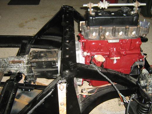
 I aimed to have 8mm radial clearance between chassis and bell housing and this entailed cutting away the arc at the bottom of the toe board, relocating the two lower hank bushes outwards to clear the lugs on the bell housing and relocating and enlarging the flange on the front of the transmission tunnel. Even if I had cut the bell housing lugs back to clear the toe board, the picture below left shows that the lower corners of the toe board arc and the existing hank bushes would interfere with the bell housing. The extent of cut to get 8mm clearance is shown in the picture below right. 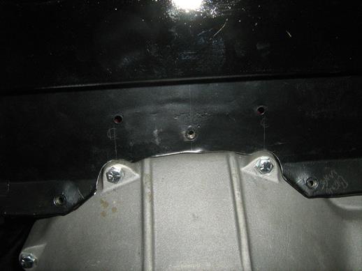
 New Rivnuts were added outside the existing holes to pick up on the relocated tunnel holes. 
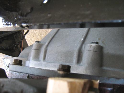
 The opportunity was also taken to remove the redundant housing for the starter motor. The tunnel modifications were laborious but uncomplicated on a bare chassis but would have been much more difficult with the body in situ. These modifications are invisible once the underlay and carpet are fitted.  A hole was cut in the LH side of the tunnel to match the location of the T9 filler plug and blanked with the MGA rubber plug. I was tempted to try to modify the T9 steel cover so that oil could be replenished through the existing filler, but this seemed to be a modification too far since the cover is an integral part of the gear change mechanism. The propshaft was fitted but there was only 2mm float on the splines. Peter Gamble said this is an occasional problem and the end float should be not be less than 10mm. I returned the propshaft and he sent me a replacement that was 15mm shorter. Speedo cable fit-up at the drive end without the transmission tunnel in place was easy, as was the fitting of the retaining circlip. But with the tunnel in place and after many attempts the circlip went into orbit for ever. One solution is to cut a panel out of the side of the tunnel to provide access but if that is done the tunnel location on the rubber buffer is lost. There are two 10mm holes in the gearbox casing just to the rear of the speedo takeoff and these provide a fixing for a clip to locate the speedo cable flange in the gearbox recess without a circlip. Easy to make and fit and a whole lot easier to remove when necessary without having to dig out the speedo recess to find the circlip. The speedo cable flange is held in place in its recess by a rubber washer cut from an old fridge motor mount. 
 There are reports that the original MGA gear lever gaiter can be restrictive. A late MGB gaiter was used along with its chrome trim which had to be bent downwards at the sides to suit the narrower MGA tunnel. The MGB gaiters spigot is oval rather than round and the circular hole in the tunnel has to be slotted forwards. The gaiter sits on top of the tunnel with its spigot into the oval hole. The trim is fixed with self-tapping screws into U nuts in the periphery of the oval tunnel cut-out and retains the carpet. 
 |