The MGA With An Attitude
FLUID LEVEL INDICATOR for the Master Cylinder - HT-202A
#2 Electrical
This is jolly good fun. It starts off as an innocent question, followed by a casual suggestion, and ends up with a new gadget.
At 11:53 AM 7/16/2007 -0500, David Broker wrote:
>"Since the brake and clutch master cylinders are really hard to get to and monitor on our Metropolitans, would you recommend the use of MC floats? Are they used in the MG world?"
I dunno about your Met. I wouldn't bother for the MGA, but someone did it once a while back. See here: http://mgaguru.com/mgtech/hydraulics/ht202.htm.
Then David wrote, "Our MCs are under the floorboards on the driver's side and a pain to get to. .... but it will get me thinking about a modified version of his solution."
Think about a fill cap with an electrical contact actuated (held open) by a float. When fluid level drops it can make a grounding contact to power a warning light on the dash. Could be very simple.
DAVID: " You were reading my mind!! However, I have zero clearance above the caps on my MCs."
You should be able to make a float switch small enough to fit under the cap inside the fill neck. It only needs one wire switched to ground. I have some devious ideas how to do that with common materials.
DAVID: "I'm trying to think through an internal hinge (inside the MC) with a float. Do you think it would be dangerous to have electronics (contact points) inside a MC?"
It should be okay. Brake fluid is flammable, but not explosive. To get a fire in the reservoir you would have to have the correct fuel/air ratio to burn, and a spark in the gas mixture (not in the liquid) hot enough to ignite it, both very unlikely. Additionally the reservoir has small volume and is capped, so even if you managed to light a fire inside it would be smothered out almost instantly. Consider that your fuel tank has a wiping electrical contact inside for the fuel level sender unit, but those never light up. Lots of cars even have an electric fuel pump inside the fuel tank, and they don't blow up either.
Then things got a little warmer.
DAVID: "I'd love to hear your devious ideas!"
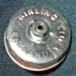
Okay, gotta love it. As a career machine design engineer, this is child's play. See attached sketch. This is a five minute invention, a five minute sketch, and a one hour description. This is based on my MGA style master cylinder with a small steel screw cap. The cap is composed of two bits of stamped sheet steel. The outer piece forms the visible outer cover with threads and a crown on top. The inner piece forms a downward pocket for splash shield, air space, and maybe a breather filter. There is a small hole in the center for reservoir venting, and it uses a cork gasket. When screwed in place it will have an electrical ground on the master cylinder via the threads.
 Find a piece of small metal tubing, preferably something corrosion resistant like copper or brass or stainless steel. It should be just large enough to pass an insulated wire, maybe 18 AWG like the normal smaller harness wiring (or slightly larger for more robust mechanical handling). Drill an enlarged hole through the center of the cap and solder the tube in place, extending downward to stop maybe 1/4-inch shy of touching the bottom of the reservoir (or higher). Nearly flush at the top is good, so you might even grind it down flush after soldering (but de-burr the inside top corner). Drill another small hole slightly off center in the cap to restore the original vent function.
Find a cork that will fit inside of the fill neck with a bit of space to spare. Find a metal eyelet, preferably corrosion resistant like copper or brass, that will have a free sliding fit on the center metal tube. Drill a concentric center hole in the cork to accept the eyelet. The eyelet could be press fit in the cork, or it could go all the way through the cork to serve as a center slip bushing, crimping over at top and bottom to be retained in the cork. The bottom end of this eyelet will ultimately be formed into part of the electrical contact. Slip this cork and eyelet assembly onto the center tube with the contact at the bottom.
Find another metal eyelet or bit of metal tubing that will fit over the center tube with generous space to spare (larger bore than the first eyelet). Place a short piece of this over the bottom end of the center tube and hold it in concentric position, extending a bit below the end of the center tube (at least 1/8-inch above the bottom of the reservoir). Alternately it may be about flush with the bottom of the center tube, but having an outward bent flange on one side at the bottom end to accept a wire connection.
Attach this eyelet to the center tube with a press fit insulated tube spacer (tiny rubber cork maybe). For first pass it might be a couple of small rubber o-rings or a dab of epoxy (or both). Maybe even fit it in place with some tape between the tube and eyelet and then a dab of epoxy. Keep the bottom end of this lower eyelet free for attachment of a wire. Keep the top end of this eyelet free and clear all around 360-degrees as the electrical contact point.
Now for the mechanical fine tuning. The top eyelet needs to have a small finger formed at the bottom on one side only, extending outward at about 30 to 45 degrees from vertical, far enough out to assure the tip of the finger will be outboard of the lower eyelet. This needs to have some angle to work, but an angle of 20 degrees or less from vertical could cause it to stick in closed contact position from friction.
Insert an insulated connecting wire down through the central metal tube. Strip the bottom end of the wire and solder it to the bottom eyelet, maintaining electrical isolation from the central tube, and not to touch the bottom of the reservoir when installed. Install whatever kind of electrical connector you like on the top end of the wire. Or make this wire long enough to reach an indicator lamp on the dashboard.
For a 50's or 60's vintage British car a wire switched to ground should be Black with a stripe. Connect a power supply wire, hot with ignition on, to the other side of the indicator lamp. This should be a White wire if direct from the ignition switch, or a Green wire if it comes from the switched fuse. Either White or Green supply can be picked up from existing original wires on the dash.
In normal operation the cork will float on the hydraulic fluid maintaining a gap between the electrical contact points. When the fluid level drops the cork will also drop. With sufficiently low fluid level the top eyelet will come into contact with the bottom eyelet by gravity to make electrical contact with the angled finger. When this happens, the angled finger will force the top eyelet off center. The top eyelet will then make another electrical contact with the center tube on the side opposite the finger. This then provides a switch grounding contact from the connecting wire to the metal cap and reservoir housing.
As the fluid level approaches the critical low level the cork may bounce around a bit on sloshing fluid making intermittent electrical contact to make the indicator lamp blink erratically with low duty cycle (more off than on). As the fluid level drops a bit lower the intermittent contact will have a higher duty cycle, more on and less off time. With sufficiently low fluid level the cork and top eyelet will sit solidly on the bottom eyelet making continuous electrical contact to keep the indicator light full on. Indicator lamp supply power should switch off when the ignition is switched off.
Note that the electrical contact points will always be submerged below fluid level, unless the reservoir would run completely dry. This will eliminate any open air arcing of the electrical contacts. The fluid will also provide constant corrosion resistance for the electrical contact surfaces. The materials used for this assembly should be compatible with and resistant to the hydraulic fluid used.
Using a common 14-volt 4-watt indicator bulb, the electrical current will be limited to about 0.3 amp. If the signal wire should happen to become electrically short circuited (grounded) inside the cap or anywhere else, the current will be the same, limited by resistance of the indicator lamp filament. Any ground fault on the signal wire will make the indicator lamp glow, same as with low fluid level.
Now if you're serious about this idea, go build one of these things, let me know how it works, and take pictures.
This design is intended to keep the working parts in simplest form for ultimate long term reliability, and to assure a positive electrical contact with the light weight (low mass) of the tiny float. Hard to beat one moving part with a loose and free-running fit. The first pass design is laid out to be built with common materials and simple hand tools so you don't need any expensive special tooling. If this was to become a production part the design would change to make the center tube crimped into the cap like a rivet rather than soldered, the eyelets would be stamped, the bottom insulator would be press fit, the bottom wire connection would have the wire end trapped between the eyelet and insulator during assembly to eliminate the soldering operation, and the top external electrical connection might be a straight male pin like a bullet connector.
And then came the payoff. At 08:36 PM 7/26/2007 -0500, David wrote:
 "Here's some of the measurements -- I used an aluminum tube as the center shaft, OD=1/4 and ID=1/16 and 2.25" long. . It was thick enough for me to put a thread on the top end (3/4" down the shaft) and then I turned 2 nuts onto the threads sandwiching the cap between the nuts. The cork (float) is: 1.25x3/8, and I used a copper tube in the middle of the cork, OD=3/8 ID=5/16 and 1/2" height plus a finger at 3/8". The larger tube is also brass OD=5/8, ID=9/16 and 7/16 height. I used a black rubber stopper as the insulator. I added a 1/16" hole to the bottom of this tube for the electrical wire."
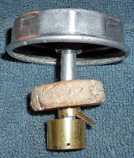
Okay, don't forget to drill another vent hole in the cap. Since the bottom end of the tube is below fluid level, without the vent changes of fluid level could make it spit fluid out the center hole. The sliding eyelet could be a little longer to reduce the likelihood of binding on the shaft when it tips. It is okay if a long sliding bushing holds the float submerged most of the time. The only concern is the last 1/4-inch of travel at the bottom when it makes the electrical contact. For a smaller diameter cap and narrow filler neck as on the MGA, the float may need to be smaller diameter (to fit through the filler hole) and maybe taller.
Now we can wait for the field report, but we may wait a long time. As long as the hydraulics hold up you may never see the light (pun intended).
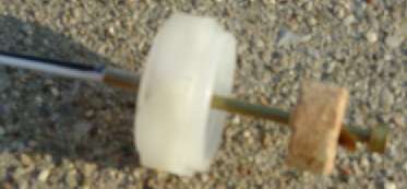
September 2008: Time flies, and here are a couple more from Michael Kelly
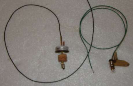
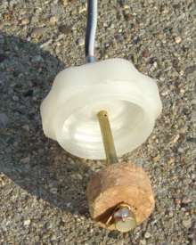 "The metal cap one has an extra vent pipe and one wire. The plastic cap one has vent drilled near the top of the cap. It also has insulated wire thru bore of tube to the bottom where contact switch 'bottoms' and other wire soldered to top of tube. This wire will need to be grounded elsewhere (since the cap is plastic)".
|