The MGA With An Attitude
Body Sill Replacement - RT-620
Closing the B-Post
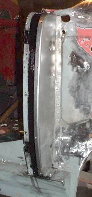
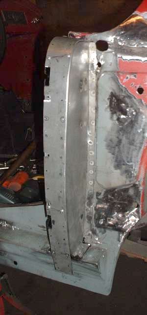
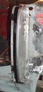
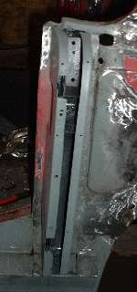
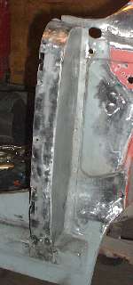
Remember the gussets I made back on page 11, and the B-post rear plates I made back on page 12? Well I finally get to install them here. The first photo below left shows the rear plate welded in place. After zinc primer and aligning and clamping the plate in place,
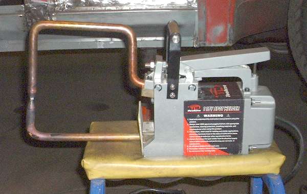
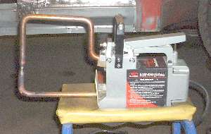 the first operation was to plug weld the plate to the flanges on the striker brace/bracket inside the post. I wasn't going to weld anything else until I was sure that was secure, as it could be a nightmare to disassemble for rework. Then the plate was clamped securely at the flanges and plug welded at the bottom and a few inches up the side of the inner sill plate. Above the sill where there is access inside the cockpit the flange is spot welded the rest of the way up. Photo at right shows the spot welder with extended tongs that allows it to reach around the door post. The plug welds were ground flat and the spot welds were sanded a bit for deburring.
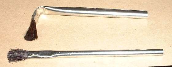
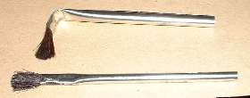 Then there was some sticky fun while coating the inside of the B-post with Chassis Saver paint which I applied using acid brushes. Those are the small paint brushes with the tubular metal handles. I bent the working end of one brush to 90 degrees to enable painting behind the outer flanges and around the striker bracket. A second brush I used straight to reach the back and sides and back corners of the box innards.
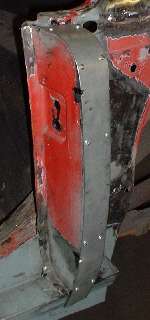
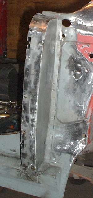
Another one of those paper templates from page 5 just came into play to layout and cut the outer closure plate for the B-post. The post is not square (orthogonal), and it is slanted on top causing a twist in the closure strip. Rather than trying to cut an exact shape for this plate I cut it a little wider than the post for the first pass. The narrow strip of sheet metal is easy enough to bend with fingers and a little roll over a round pipe. In a few minutes I had it close enough to the right shape that is could be held snug against the post with light finger pressure. The second picture above shows the top end of the strip tucked under the body tonneau rail, and the rest of it secured temporarily with a number of small sheet metal screws. Once secured I made a scribe line around the reverse side of the strip using the post sides as a guide. Then the strip could be removed and the edges ground back to the line for the finished width.
Notice also in the same picture two small notches in the front edge of the strip. These were cut in line with the small slots in the front plate where the door buffer screws will be installed. These notches can then be used as reference for laying out and cutting the larger notches for the door buffer, and also to reference the location of three more small clearance notches for the screws for the shut face plate (and front edge of the rear wing).
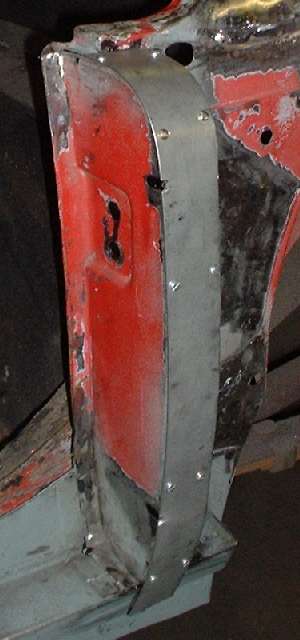
The third picture above shows the closure plate held with only four screws while test fitting after finishing the width and cutting the notches. Notice also a number of black dots marked where I will punch holes for plug welding. The forth picture above shows the welding surfaces of the open post sprayed with the zinc paint.
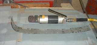
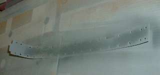
Now here is the finished closure plate with the plug welding holes punched. The picture above also shows the air tool used to punch the holes. This is a dual purpose tool with a flanging die near the end that will press an offset in the edge of sheet metal to provide a lap joint for welding. That function will most likely not be used during this project. The second slot from the end contains the 1/4-inch punch and die for making the plug welding holes. Held square against the edge of the sheet metal the tool will punch a 1/4-inch hole 5/16-inch from the edge. In this case I held the tool slightly askew to punch the holes only 1/4-inch from the edge. Photo on right above shows the closure plate coated with zinc paint on the inside surface, ready to be welded in place.
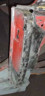

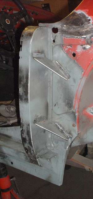
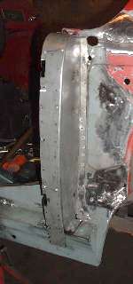
During initial welding the closure plate was held in place with all ten screws to be as secure and intimate as possible for plug welding. Then the screws were removed, and the screw holes were also plug welded. The bottom end of the plate was then hammered a bit to be flush against the sill box panel for plug welding there. All plug welds were then ground flush ready for painting. The final picture shows the triangular gussets installed (with zinc paint in the joints). The top one was spot welded to the inner body while the other three flanges were plug welded and ground flush. About this time a friend came for a visit, and we had a jolly good time wailing on the sill and pillars with a 2-pound dead blow hammer just to demonstrate how solid this construction is. (7 Mar 08)
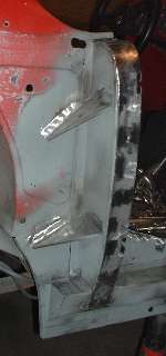
Skip ahead two days, and the last picture shows the right side B-post closed in the same manner with the gussets installed. I changed the sequence a little here, installing the rear plate and then welding the gussets before painting inside the post. That way plug welding the gussets to the post does not burn the paint off the inside of the post. (9 Mar 08)
|