The MGA With An Attitude
Body Sill Replacement - RT-627A
Holes in Lower Edge of Body Sill
Addendum 25 MAY 09 (more than one year later)
I knew this would eventually spawn some questions and more answers, so here goes.
At 09:01 AM 5/25/2009 -0600, Fredys Medina on Canary Island on Spain wrote:
"I can't find the correct distance between holes on the lower part of front and rear fender for fixing with the inner sill."
Are you concerned about concours show judging on this point? I think if you get the original number of screws of correct size in about the right locations, probably no one will ever use a tape measure to check if they are exactly right. The nature of restoration work commonly dictates that new or repaired panels are massaged in process to fit up to mating panels. As such, the final assembly panels will not necessarily be perfectly interchangeable with original panels.
When finishing up my body restoration work about this time last year, I had left those spots in the inner sills blank until very late in the project. For a long time I had the fender bottom edges clamped to the inner sills. The holes were drilled for those screws after all body work, panel alignment and surface prep, and just prior to outer coat painting.
My front fenders still have the original bottom edges, so I can confidently get the correct location for those screws. I did replace the rear wing doglegs last time around, so my new screw locations there may be best guess near to original locations. I have just measured my car to get these dimensions.
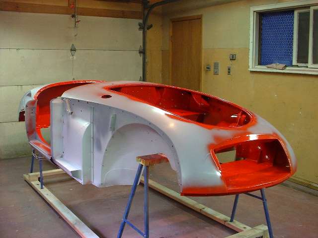
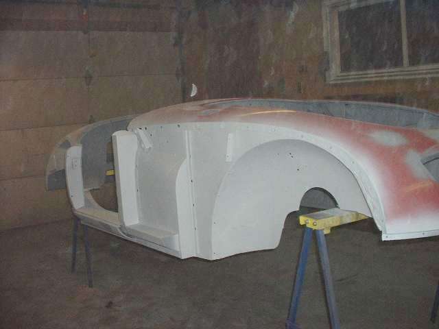
 See these pictures for reference:
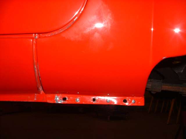
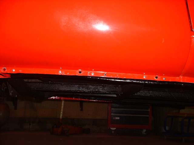
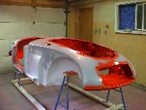
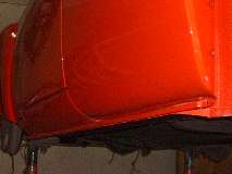
Notice no holes in the sill in the first picture, but the holes are there in the second picture. About 5" aft of the inner fender arch there is a flat outward step in the body shell. I will call this the "body step", and I will use this as the point of reference for the sill screw locations.
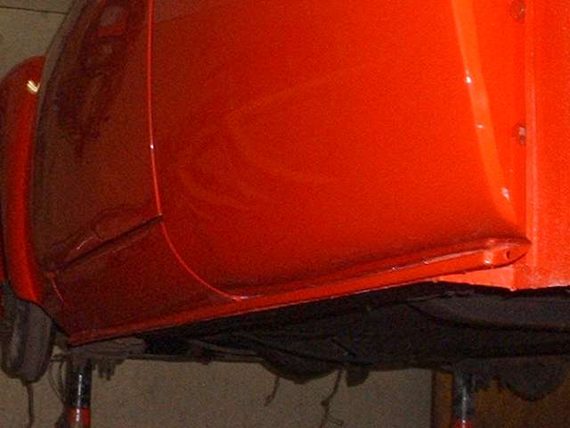
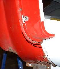 The first hole is just 3/4" aft of the body step, immediately aft of the spot weld flange. There should be a short slot in the front fender flange at this point. Going to the back of the fender flange, about 2" forward of the rocker panel, there would be another screw with hole in the sill and slot in the fender flange. Split the difference between these two locations to find a third screw for the fender to sill joint, again a hole in the sill and slot in the fender flange. See more photos below.
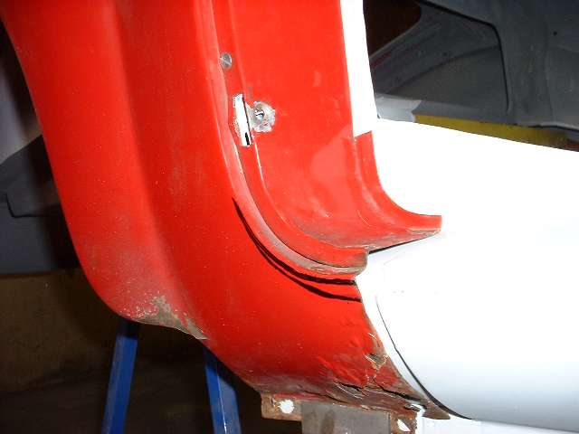
The rear fender dogleg has two screw locations, about 3/4" from each end of the dogleg flange with holes in the sill and slots in the flange.
Very early production MGA had no lower body trim strip, so these five screws securing the fenders on each side were in plain sight.
The SPL calls these screws AFH2587. These are #10-32-UNF x 1/2" long pointed tip screws with 3/8" hexagonal head. Include LWZ203 spring lockwasher (zinc), PWZ203 #10 plain flat washer (zinc), and AFH2546 Washer Plate. This last piece is a rectangular flat washer that will not protrude below the bottom edge of the flange. There is no nut specified here because original assembly had a #10-32-UNF square nut in a sheet metal cage spot welded to the inner side of the sill (five places each side). The washer plate, flat washer, lockwasher, and hex head all went on the outside in that order, and I think all this was painted over (touched up) after assembly for the early cars with no trim strip (but I could be wrong).
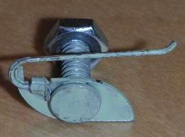
 In Sept 1956 at Car No. 19949 the sill finishers were added. This did not change the fasteners used to secure the fender flanges, but some additional holes were added to the sill and fenders to accommodate five new screws each side to secure the trim strip. These will be AFH3752 special T-bolts with #10-32 threads. On the inboard side of the sill add PWZ203 #10 plain flat washer (zinc), LWZ403 #10 internal tooth lockwasher (zinc), FNZ103 #10-32-UNF hex nut (zinc). The spring loaded T-bolt shown here (very easy to use) was supplied by Moss Motors for many years. In 2009 the design was changed by the manufacturer, and it no longer fits inside the trim strip. Subsequently Moss Motors has reverted to supplying original style T-bolts with plain rectangular head.
 Note that the inside dimension of the finisher strip is quite narrow, such that the hex head screws holding the fenders may need to be turned with flat sides parallel to bottom of sill to fit inside of the finisher strip. Even then the stack of washers might interfere with flush seating of the finisher strip. I don't recall ever seeing one of these in original assembly, as the cars I bought in the late 60's had already been repainted once.
As a matter of convenience, during assembly I was using 1/4-inch screws to secure the fenders. Just before installing the finisher strips I drilled 1/8" holes and installed pop rivets, then removed the bolts, leaving only the pop rivets in place before installing the finisher strips.
Note that the inside dimension of the finisher strip is quite narrow, such that the hex head screws holding the fenders may need to be turned with flat sides parallel to bottom of sill to fit inside of the finisher strip. Even then the stack of washers might interfere with flush seating of the finisher strip. I don't recall ever seeing one of these in original assembly, as the cars I bought in the late 60's had already been repainted once.
As a matter of convenience, during assembly I was using 1/4-inch screws to secure the fenders. Just before installing the finisher strips I drilled 1/8" holes and installed pop rivets, then removed the bolts, leaving only the pop rivets in place before installing the finisher strips.
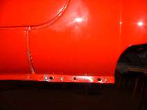
Screws for the finisher strips are located as follows. The first one is 2-1/2" forward from the body step, meaning it is only attached to the fender flange, not to the body sill. The second one is 11-1/4" aft of the body step in the fender flange and body sill. I'm pretty sure these are original locations, following the holes in my original front fenders. The fifth screw (at back) is 50-1/2" aft of the body step. This puts it midway between the two screws that would secure the rear fender to the body sill, as seen in the picture above right. I'm pretty sure this is also original location following holes in my original doglegs. The remaining finisher screws are 24-1/4" and 37-1/2" aft of the body step. These fall on the flange of the rocker panel below the door. I do not know if these are the exact original locations but they are spaced about evenly 13" to 13-1/4") between the other finisher screws, so it is a good bet they are within a half inch or so of original location.
There is one more hole in the front fender flange 4-1/2" forward from the body step. This is for the screw to attach bottom end of the splash panel to the fender flange. The finisher strip should be 57 inches long tip to tip. When the finisher strip is properly installed it does NOT cover this forward screw. This screw head is intentionally left exposed so you can R&R the splash panel without removing the finisher strip. This screw should be #10-32-UNF x 3/8" Round Head with Phillips slot. On the inboard side add flat washer, lockwasher and hex nut, all zinc plated.
Considering original sequence of assembly, the body was painted first, then assembled, and the finisher strips were installed after the fenders were in place. The finisher strips were always painted same color as the body, and I'm pretty sure they were originally painted before installation. This means the front screw securing the splash panel was most likely not painted. Since zinc plated screws will eventually rust with time, some people prefer to substitute a nickel plated screw here, and even though it is not strictly original I don't suppose it would lose points in concours show. For myself, I would just use a zinc screw and let it rust, or paint over it later for touch up, as I am not a concours buff (but I do like the finisher strips).
|