The MGA With An Attitude
Master Cylinder Mounting Change - MGA Twin Cam - TC-206
MGA Twin Cam Master Cylinder Mounting Modification
At MGA Twin Cam chassis number 997 the mounting box for the clutch and brake master cylinders was modified. There is no reference to this change in the Twin Cam Workshop Manual and a BMC Service Memorandum on the subject cannot be located. The only references found are in the Twin Cam Service Parts List and the book Original MGA by Anders Clausager (pages 74 and 88).
As stated in the Service Parts List the parts changed were:
Master cylinder mounting box (AHH5684 superseded by AHH5877)
Reinforcing plate (AHH5685 superseded by AHH5876)
Two bolts that locate the brake master cylinder (HZS0513 superseded by HZS0510)
Two tapered shims (AHH5874) were deleted.
The Service Parts List also shows that the clutch master cylinder never had tapered shims.
The changes to the Twin Cam unique mounting box and reinforcing plate could only be determined by examination of samples of both the early and later parts. The early mounting boxes had the clutch and brake master cylinders at the same height (see diagram below). The mounting holes for the brake master cylinder only were lowered by 1/8 (both the large hole and the two bolt holes) for the later cars. The curve in the side of the box was also increased [to improve access to the master cylinder brake line fitting, much more important on right hand drive cars].
The early type brake master cylinder locating bolts were zinc plated, hexagon headed bolts, 5/16 UNF, threaded full length and 1 5/8 long. The later bolts were of the same type but 1 1/4 long as they did not have to locate the deleted tapered shims. The details of the bolts are documented in the BMC Standard Fasteners publication.
Compared to a pushrod MGA, on the Twin Cam the length of the brake pedal lever, from the lever pivot centre to the clevis pin centre, is shorter by 1/8. This shorter upper section of the brake lever caused misalignment of the brake master cylinder pushrod, which placed an unacceptable side load on the piston. Fitting a tapered shim gave the brake master cylinder a downward slope towards the front but restored the correct pushrod alignment, and thus removed the side load on the piston. It also improved access to the hydraulic pipe fitting. To get this downward slope a tapered shim is fitted between the master cylinder and the mounting box with the thick end down. However, bolts can only properly clamp surfaces which are parallel, so another shim is fitted in front of the mounting box with the thick end up. When one shim is fitted inside the box and one outside, one with the thick end down and one with the thick end up, the master cylinder has a slope but the bolt heads and their nuts rest on parallel surfaces, as they must for proper clamping and to avoid placing bending loads on the bolt. This also then has the bolts the same length, as per the Service Parts List.
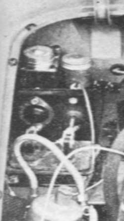
The photo above is from the UK magazine The Motor of the 16th. July 1958. It is a factory demonstrator car. This shows that the requirement for shims was known to the factory when the first cars went on sale, and it appears that approximately 500 mounting boxes had already been manufactured.
Subsequent procurement orders for the mounting boxes had the design altered to lower the brake master cylinder. At the same time the curve in the side of the mounting box was increased to give better access to the hydraulic pipe fitting, particularly on right hand drive cars.
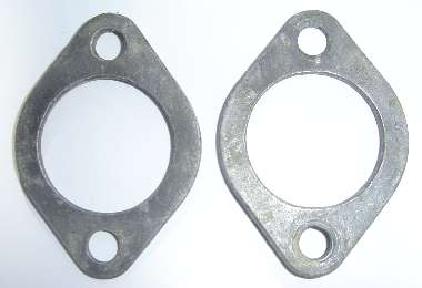
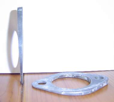
These shims can be made if required. See drawing below. They are oval in shape with a top to bottom measurement of 3.000" and a side to side measurement of 2.125". They have a straight taper top to bottom with a thick edge of 0.223 and a thin edge of 0.067. The holes in the shim can be made using the mounting box reinforcing plate as a template. The holes are centralized in the oval, horizontally and vertically.
Note: If any shims were fitted, in error, between the clutch master cylinder and the mounting box and are removed, the free play of the pushrod for the clutch master cylinder must be checked. Refer to Adjustment in the clutch Section E of the Workshop Manual. If any shims between the brake master cylinder and the mounting box are removed, added, or changed in orientation, the free play of the pushrod for the brake master cylinder must be checked. Refer to Adjusting the brake pedal in Section M of the Workshop Manual.
Summary
On cars with chassis numbers 501 to 996, a tapered shim with the thick end down is fitted between the brake master cylinder and the mounting box as shown in the Service Parts List. An identical shim is fitted outside the box with the thick end up.
If the clutch and brake master cylinder mounting holes are at the same height in the box it confirms that it requires the shims to be fitted.
If the brake master cylinder mounting holes are at a lower height than those for the clutch master cylinder no shims are required.
This allows identification where only one mounting box is available and the curvature of the side of the box cannot be compared with other units.
The clutch master cylinder does not have shims on the early cars, nor the later cars.
The late
Blake Urban
South Dakota USA
Addendum, February 2010:

This article is truly a product of international cooperation. The original photo was from "The Motor", a UK magazine, in 1958. The shims and pedal box change are mentioned by Anders Ditlev Clausager in "Original MGA" (a UK publication) in 1993. The article above was originally written by Blake Urban (now deceased) in South Dakota, USA, accompanied by a rough sketch of the part. This was provided to Mick Anderson in Australia who subsequently passed it on to me in 2005. While I was making the CAD drawing, in 2010, Klaus Junker in Germany was measuring original parts and sending the accurate dimensions. Phil Vanmale in the UK then provided the follow-up pictures, also of original parts. (Small world). Incidentally, the original parts were made from aluminum, and they appear to have been cast (beveled adges on one side).
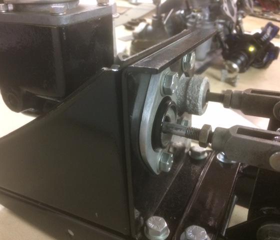
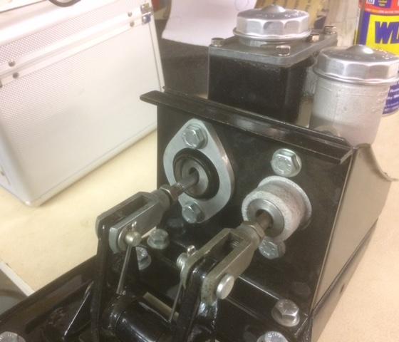
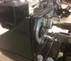
Photos below compliments of Kevin Bruce in North Richmond, NSW, Australia, 20 Dec 2018.

|