The MGA With An Attitude
DUNLOP HAND BRAKE FUNCTION - TC-207A
Written by Mick Anderson in Australia
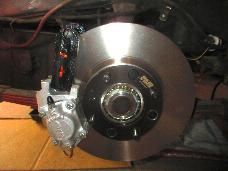
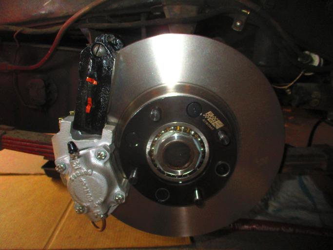
The following is a description of the method of operation of the rear handbrake of the Dunlop brake system on the MGA Twin Cam. This should be read in conjunction with the Workshop Manual and the factory Service Parts List. A diagram from the Workshop Manual is included in this article.
Firstly, a list of the items referred to later and shown in diagram here.
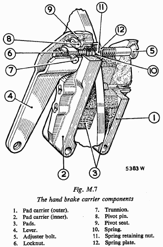 Operating lever (item 4).
Pivot pin with split pin fitted (item 8).
Pivot pin seat (item 9)
Trunnion, brass (item 7).
Nut, self-locking (item 6).
Pad carriers, outer and inner (items 1&2).
Caged nut, brass (item 11).
Cage for nut (item 12).
Spring (item 10).
Adjusting screw (bolt) (item 5).
Brake pads, inner and outer (item 3).
Operation:
The handbrake cable pulls the operating lever away from the assembly. As it moves away it pulls on the trunnion pivot axles (item 7). The trunnion, which is not threaded, pushes against the self-locking nut (item 6). The selflocking nut pulls on the adjuster screw (item 5), which pulls the outer pad carrier and pad onto the disc. The trunnion axles, now unable to move further, have the effect of a pivot, causing a force to be applied to the upper pivot pin (item 8). The part of the lever at the upper pivot pin, through the pivot pin and seat, forces the inner pad carrier towards the disc and the inner brake pad onto the disc.
Secondary operation:
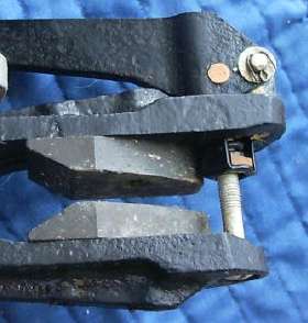
There is a caged nut, with the cage rivetted to the inner pad carrier (items 11&12). This brass nut is threaded onto the adjuster bolt. Between the caged nut and the inner pad carrier, and seated partially inside the carrier, is a spring.
When, during operation, the adjusting screw pulls the outer pad carrier towards the disc it also moves the threaded caged nut towards the inner pad carrier and so compresses the spring. When the handbrake is released, the spring can expand and push the inner pad carrier in the opposite direction to which it pushes the caged nut and the adjuster screw. This restores the original distance between the inner pad carrier and the head of the adjusting screw at the outer pad carrier, allowing the total pad clearance to be possible again, but does not ensure that each pad is equidistant from the disc. Also, the outer pad carrier arm is able to move back and forth slightly due to the side clearance between the adjuster screw and the arm, together with the domed shape under the screw head. Later versions of the handbrake on other cars (not the Twin Cam) had a two pronged retractor spring to overcome this.
Notes:
The trunnion pivot axles also allow the trunnion to have 100% surface contact with the self-locking nut during operation, even when movements of the operating lever and/or the adjusting screw could otherwise cause uneven contact. For the same reason the underside of the screw head, and its seat, have a spherical shape. Also there is a large clearance between the shaft of the screw and the hole in the pad carrier.
The item described in the Workshop Manual as a locknut is more accurately described as a self-locking nut. As the nut itself cannot turn due to the hexagon being fitted into a recess in the operating lever, the self-locking ability is to prevent the adjusting screw from turning, except when being adjusted.
The pivot seat (item 9) provides a stronger fitting between the pivot pin, operating lever, and the inner pad carrier. It fits into a hole in the inner pad carrier.
Correct adjustment is to unscrew the adjustment screw one third of a turn back from the point where the brake pads are in contact with the disc.
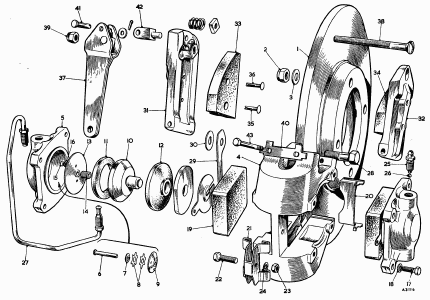
Click for larger pdf file image of this brake parts explosion diagram.
|