| The MGA With An Attitude
Twin Cam Engine GENERAL DESCRIPTION - TC-300
Four engine photos here have been procured from
the MGA Twin Cam Enthusiasts email group
with permission from Bernard Lien-Lambert in England.
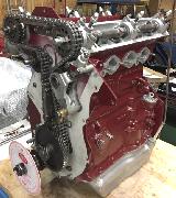
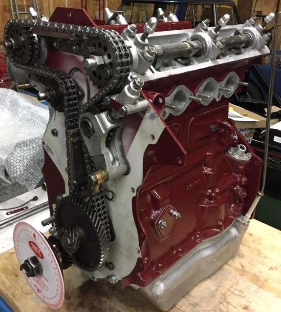
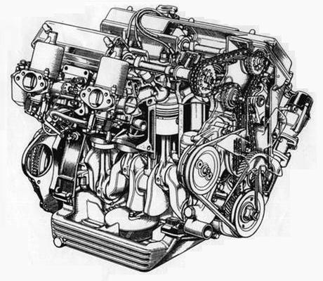
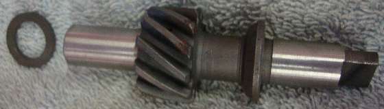
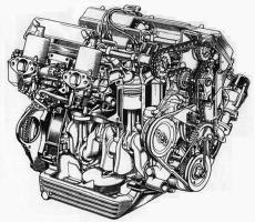
The MGA Twin Cam engine was derived as an extensive modification of the Austin B-series 1500 cc pushrod engine with larger bore for 1600cc displacement and a slightly stronger crankshaft extended at the front end (and forever unique to the Twin Cam engine) and incorporating a "rope" style rear seal. The in-block camshaft is retained in rudimentary form (called "half speed shaft", gear driven and counter-rotating) to drive the oil pump and the tachometer drive cable, and is generally referred to as the half speed shaft.
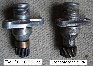
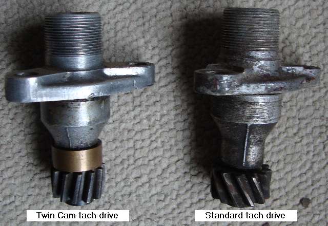
Using the same oil pump, the half speed shaft and the oil pump and tach drive gears have helical gear teeth spiraling in the opposite direction to maintain proper rotation for the oil pump and tach drive. With opposite angle on these gear teeth the thrust on the oil pump drive spindle is upward toward the block rather downward against the oil pump, and upward against the tach drive housing rather than downward on the block. The Twin Cam engine then has an additional thrust washer at top end of the oil pump drive spindle and above the tach driven gear.
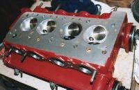
 The cast aluminum twin cam cylinder head has the valves canted at a 40 degree angle from vertical (80 degrees included angle) forming a cross flow "hemi head" combustion chamber that allows for use of much larger valves, and accompanied by high crown pistons. The valves are driven by overhead camshafts which are chain driven from the half speed shaft by a long roller chain guided and adjusted by two idler sprockets (therefore rotating opposite direction from the crankshaft). Valves are pressed by inverted bucket tappets with valve lash adjusted using button shims. Early engines used short tappets in alloy bores. Later production used longer tappets running in iron bore liners. A further refinement used better alloy steel tappets with a small chamfer at top edge to be identifiable at a glance.
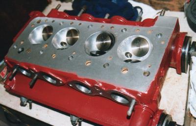
 There were a few very early prototype engines fitted with adjustable tappets on fat threaded valve stems. This arrangement turned out to be weak and prone to breakage at high engine speed. It is thought that none of these engines should ever have escaped the Morris Engines Branch in Coventry, not even to MG at Abingdon. Peter Wood reports having worked on at least one of them much more recently, so perhaps one or more of the prototypes has survived. The pattern of head bolts is rearranged, particularly on the exhaust side of the engine, to allow four discrete exhaust ports (in the absence of pushrods), and four separate intake ports. Thus we have an eight port cylinder head where the pushrod engine had only five ports (two intake and three exhaust).

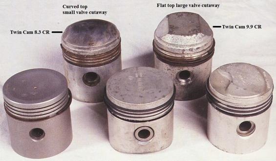
The Twin Cam pistons had a hemispherical design highly crowned on top. Most were originally high compession with 9.9:1 compression ratio. Very late in production the compression ratio was lowered to 8.3:1 using lower crown pistons. See Confidential Service Memorndum MG/325.
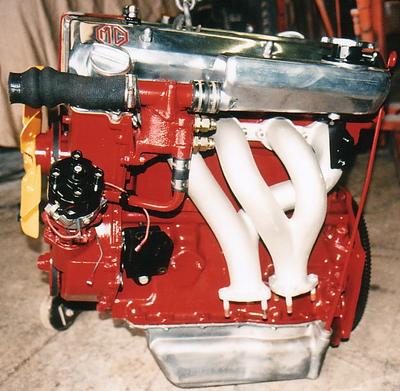
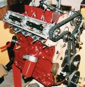
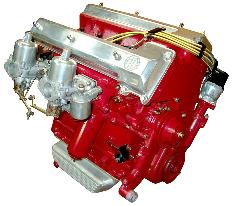
 The Twin Cam distributor is at the front left side of the engine, mounted in the new taller cast aluminum timing chain cover, and the earlier distributor drive boss on the right side of the block is left blank, not machined. Dual SU H6 carburetors are mounted on the right side of the engine. Spark plugs are on top down the center of the cylinder head. The heater water valve is different and is mounted at the front of the heater box on the heater inlet pipe.
 One of the most unusual design features is that the water pump only feeds water to the cylinder head, not the block. The water pump takes water from the radiator by a unique fitting at the bottom of the pump, and then expels it from the rear of the pump into a pipe. This pipe takes the water to the rear right side of the cylinder head and then it exits from the front left side of the head to the thermostat housing and then the radiator. A small pressure differential from back to front moves water downward from head into block at the back, then back to front through the block, then upward from block into head at the front. This unusual system is required because the front engine plate extends from below the crankshaft to the top of the cylinder head and so blocks off the opening in the top front of the engine block.
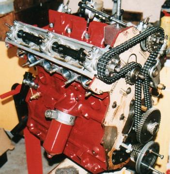
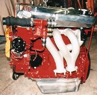
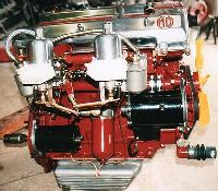
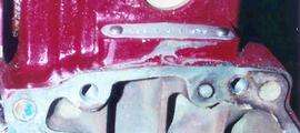 The engine number plate is attached on top of the block at the back of the engine. The oil filter is mounted in the original position on the right side of the engine. The oil sump is enlarged, particularly in width, and fabricated of cast aluminum. The Twin Cam engine rear plate incorporates the high starter position to match the gearbox. Water pump, cooling fan and generator are still belt driven, but the generator has a larger pulley so as not to run too fast with the intended higher engine speed. Early in production the generator pulley was reduced in size for better battery charging at low engine speed, but was still larger than the pulley on a pushrod engine. Picture above shows an incorrect generator with wrong end plates, fan and pulley from a pushrod engine (and misaligned fan belt). See article TC-314 for more information on generator fan and pulley variations.
The right side engine mount is different for the Twin Cam and "Deluxe" cars, but the right side bracket is same for all MGA. Left side engine mount is same for all MGA, but the left side bracket is different for the Twin Cam (very rare and difficult to find). So, the "Deluxe" cars have right side engine mount of the Twin Cam, and left side bracket same as all push-rod cars. (Click for larger pictures above).
The Twin Cam radiator is positioned farther forward, requiring complimentary changes to the radiator (shorter height), the radiator mounting diaphragm, and the horizontal air pan ahead of the radiator. There is also a remote expansion tank for the cooling system located high at the left side of the engine and attached with a pair of bolts to the rear branch of the exhaust header casting. A thermostat housing is located between large hoses just ahead of the remote tank. After a short period of production the remote tank got an even more remote pressure relief valve connected by the small overflow hose.
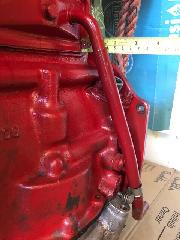
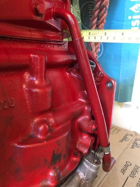
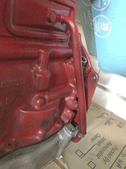
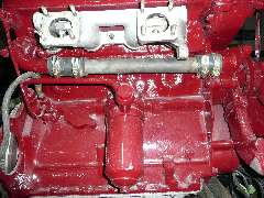
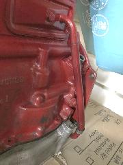 A crankcase vent tube is attached to the rear side cover (tappet cover for the pushrod engine). For early Twin Cam engines, the bottom bracket is attached with a 5/16 UNF bolt which screws the block behind the dipstick tube (photo at left). You cannot fit the bracket with the dipstick tube in place. For later Twin Cam engines, the bottom bracket is attached with a 5/16 UNF bolt through the engine back plate (photo at right). This has different part numbers for the rear side cover and vent tube, and they are not interchangeable.
|