The MGA With An Attitude
Coolant REMOTE PRESSURE RELIEF VALVE - TC-325
Animated illustration by Barney Gaylord
Photos and notes by Mark Wellard in Australia
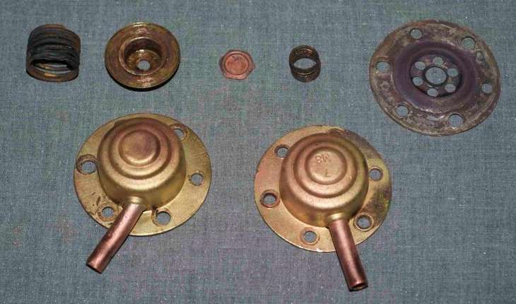
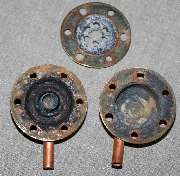
 The pressure relief (or last chance, according to Jim Alcorn) valve was dismantled and new rubbers inserted before reassembly. The parts manual does not have an exploded diagram, so improvisation was the order of the day!
Working out the position of the rubber was the big challenge when it s in this condition! Looking at the shape of the seating surfaces was the only guide. There appears to be facility for a large diaphragm seating against the perforated center plate. Another small spring-loaded valve operates within the center section of the main sliding valve, held in place by a small spring.
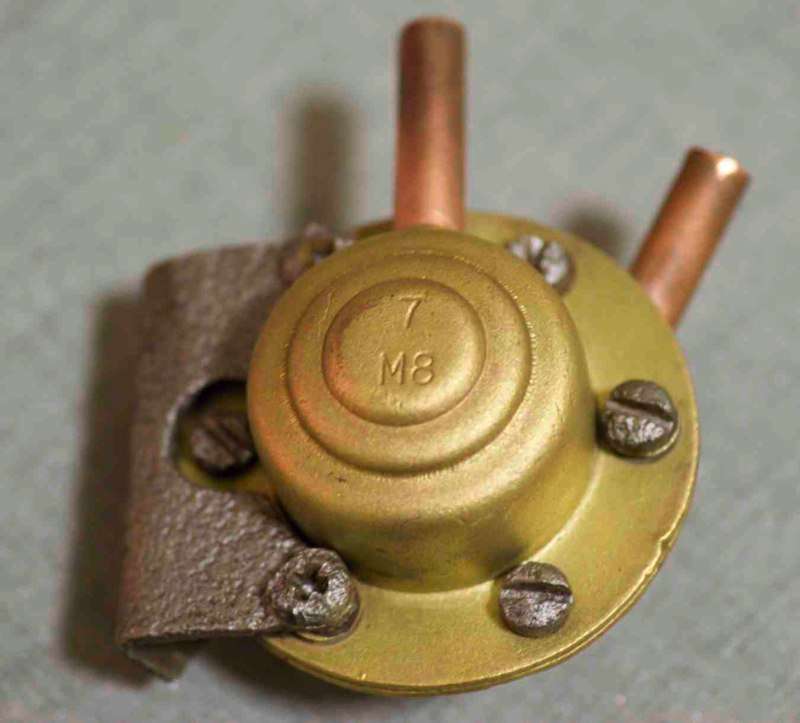
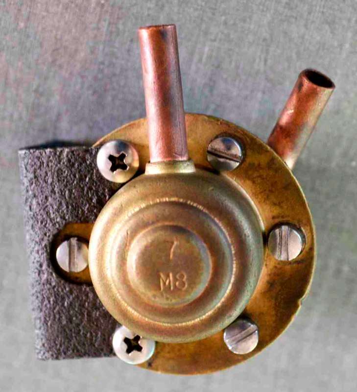
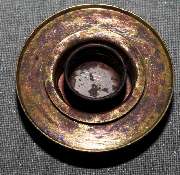
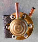
A: Before dismantling - bracket held by Phillips pan-head screws, other 4 holes are standard pan-head screws.
|
Coolant Pressure Relief Valve
Click For Animation
Then see How It Works farther down.
|
|
|
|
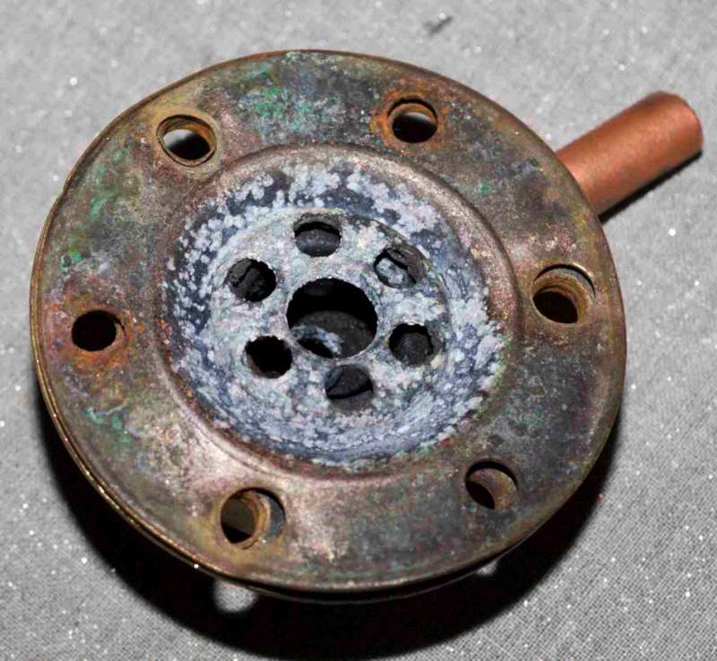
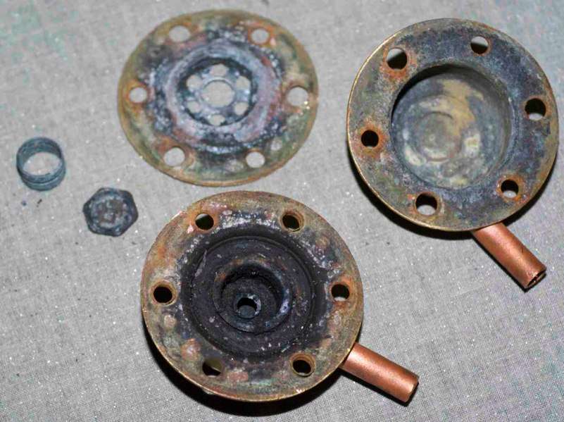
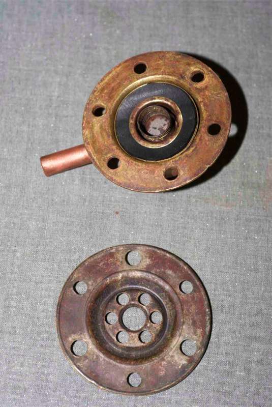
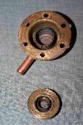
B: Working half - note the 3 eye-rivets holding the separating plate in alternate holes at 2, 7 & 11 o clock.
|
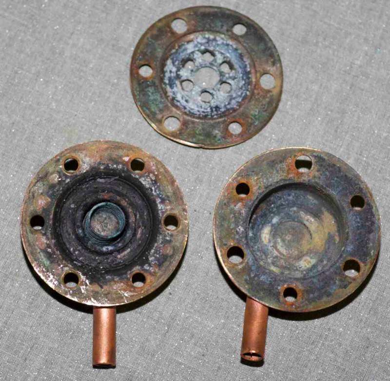
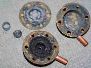
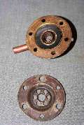
C: Main valve seating surface removed, showing support plate and poppet valve. The other half of the chamber is empty.
|
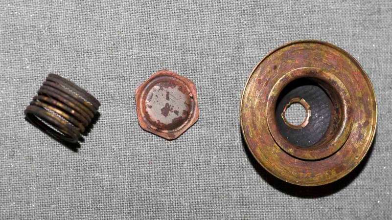
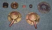
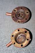
D: Full disassembly showing the main valve and spring (top left) and poppet valve (center).
|
|
|
|
D2: Top layer. The center plate has been levered off the rivets which, with care, can be reused.
|
E: Rubber inserted into the main valve body for the poppet valve.
|
F: Poppet valve in place.
|
|
|
|
G: Main valve spring and valve body.
|
H: Rubber inserted onto main valve seating surface
|
I: Valve seat in place, ready for final assembly.
|
|
|
|
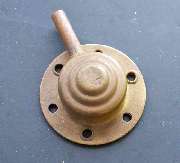
J: Reassembled and ready for paint - black or body colour?
|
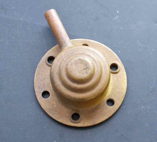
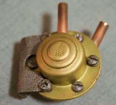
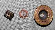
K: Top cover of a new unit showing three eyelet rivets.
|
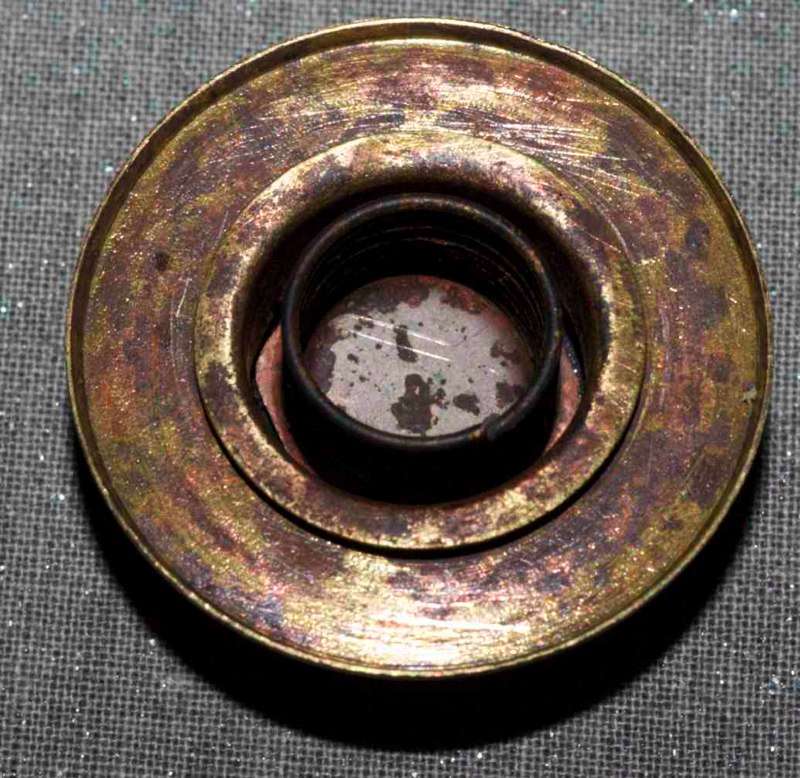
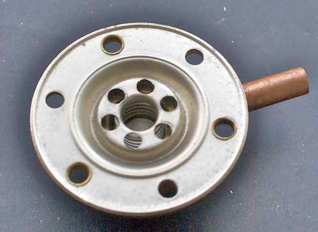
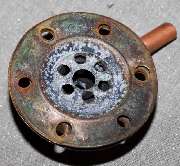
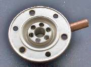
L: Top cover inverted showing working parts inside.
|
Note it has K7 stamped in the top, probably referring to the 7lb relief pressure.
There was originally a thin cork gasket between the two halves I sealed mine with silicone sealant. I also used thin bicycle tube as a replacement for the rubber seals. The diaphragm is stamped and does have a gasket ridge on the surface away from the valve mechanism. I can't see evidence of sealant between the
diaphragm and the shell it is riveted to.
When reassembled, it is surprising how little resistance there is - I guess 7 lb is not much pressure; together with old springs it means there is probably room for improvement.
Comments on the accuracy of this reassembly would be welcome. -- Mark Wellard
How It Works
Follow-up notes by Barney Gaylord
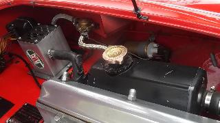
The radiator and reservoir tank are plumbed onto the (empty) lower housing port, while the vent and overflow hose is connected to the upper housing port. When coolant fluid expands it will push the valve plate upward to allow fluid (mostly air in normal operation) to escape past the larger seal and exit via the top vent port. The large spring then controls the 7-psi relief pressure. When coolant fluid contracts it will allow atmospheric air pressure to upset the smaller poppet allowing air to enter via the small hole in the valve cup. The smaller spring is then controlling perhaps 2-oz per sq-in return flow pressure differential. As coolant fluid contracts when cooling, atmospheric pressure can easily push air back into the reservoir to prevent collapsing a radiator hose (from possible vacuum inside).
For the the most part, fluid going through the valve is supposed to be air, not water. Outbound fluid might be moist air, while inbound fluid may be dry air. If the engine might overheat and boil the coolant, then expelling copious amounts of fluid, the fluid being expelled would be steam, possibly with some water droplets in suspension. Since there is a substantial reservoir in between the radiator and this valve, steam escaping from the radiator would immediately condense into liquid in the reservoir, until the reservoir liquid may be brought up to boiling temperature throughout.
When the reservoir liquid is at boiling temperature, then steam under pressure would be pushed out through the relief valve. As the pressure drops the "super heated" steam and vapor mixture should expand and flash off any liquid droplets into steam immediately at the pressure relief point. When steam passes through the vent hose and escapes to atmosphere it will cool and condense back to boiling temperature water droplets. Since the top half of the relief valve is at low pressure, and it is likely to be cooler than boiling coolant (air cooled), there would be both flash off and condensation going on in the top chamber. There will then be a small amount of liquid coolant there until it may be expelled via the vent port. In the end you have a little puddle of liquid in the top chamber below the vent port. If there is no gasket there, then liquid would spill out between the riveted flanges.
If you overfill the reservoir, then thermal expansion will expel liquid through the PR valve the first time it warms up to operating temperature. That should be the exception to the rule and should only happen once (unless you then overfill it again later). Expulsion of lower temperature liquid would also leave liquid in the top part of the PR valve, which would subsequently leak out the flange if there was no gasket on the top side.
So far two people have said there is no gasket in the riveted side of the canter diaphragm. I don't think the designers had in mind for this valve to be regularly dripping liquid out the sides of the flange above the diaphragm. There must have been some sealant in there, even it was painted on with a brush before riveting. I would certainly seal it during any reconstruction work.
This tech page has been brought to you by the part number AHH5903
For rmore information about this part number and associated parts and fasteners, see Part Numbers tech page: AHH5903.htm -- Relief valve and cage assembly
|