The MGA With An Attitude
BALANCING PEG DRIVE WHEELS - WL-111
At 01:13 AM 3/20/05 +0000, Mitch (anonymous) wrote:
"I had my tires mounted on my (Twin Cam) rims today, and the tire shop could not balance them, due to them not being able to properly center the wheel because of the pegs sticking out. .... How do people balance these wheels? .... They suggested I take the pegs out but I declined."
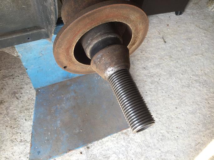
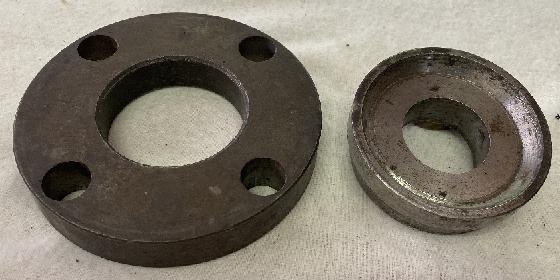
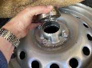
The Dunlop steel wheel used on the MGA Twin Cam and "Deluxe" model cars has four taper nose pegs with cylindrical shanks to locate and drive the wheel. These pegs will interfere with fixturing on a modern spin balancing machine.
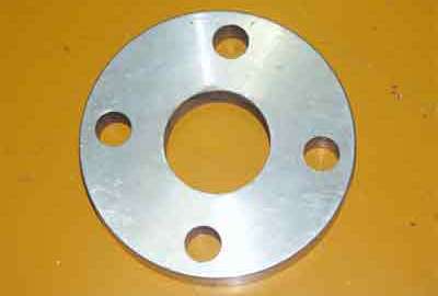
To mount this wheel on a spin balancing machine the pegs must be covered and the wheel must be centered relative to the pegs. To accomplish this a special fixture plate is required. The picture here shows one made from aluminum. The plate is thick enough to cover the full height of the pegs, has four holes accurately machined for a very close fit on the pegs, has a center hole which is absolutely concentric relative to the circle of the four pegs, and is flat and parallel on both sides.
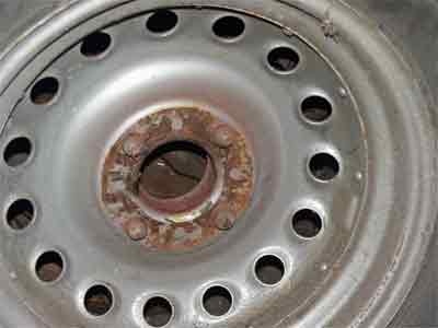
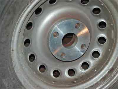
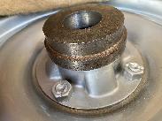
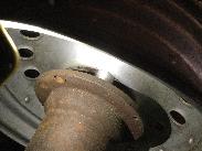
The picture below shows the adapter plate installed on the pegs inside the wheel, ready for mounting on the spin balancing machine.
Thanks to Bill Spohn <WSpohn4@aol.com> for the adapter design and pictures.
At various times this adapter might be purchased from Ralph Zbarsky <zedeng@shaw.ca>. Last reported price was $42 delivered to your door in North America (overseas extra). As of June 2018 Ralph is not making these parts any more (better things to do with his life).
Click for printable PDF copy.
Print on ANSI B-size paper 17 x 11 inches with 1/2 inch margins.
Be careful with the idea of powder coating your Twin Cam wheels. If you paint the pegs the wheels will no longer fit on the car, and you will subsequently spend a lot of time removing the power coating from the pegs.
On 6/27/2018, Ralph Zbarsky wrote:
"I measured some rear hubs, holes average at 0.742 diameter... which must be why I made the adapter holes 0.752 or so. The drive pegs on one spare wheel average to 0.741 with powder coating, so no wonder I need the BF lead hammer, and lots of wiggling".
NOTICE: The outside end of the hub seems to call for a female cone adapter similar to the one used for balancing wire wheels (see previous page). However, this outer cone adapter is not nearly as critical here (since the wheel is centered by the drive pegs). For wire wheels the hub needs to be mounted on two cones with no contact on the inside flat surface. The peg drive wheels are mounted on the inside flat surface and will be centered with the wheel pegs. A female outboard cone fixture is optional as a convenience (and is recommended) for clamping the wheel in the balancer machine.
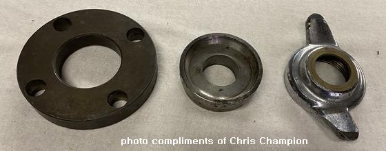
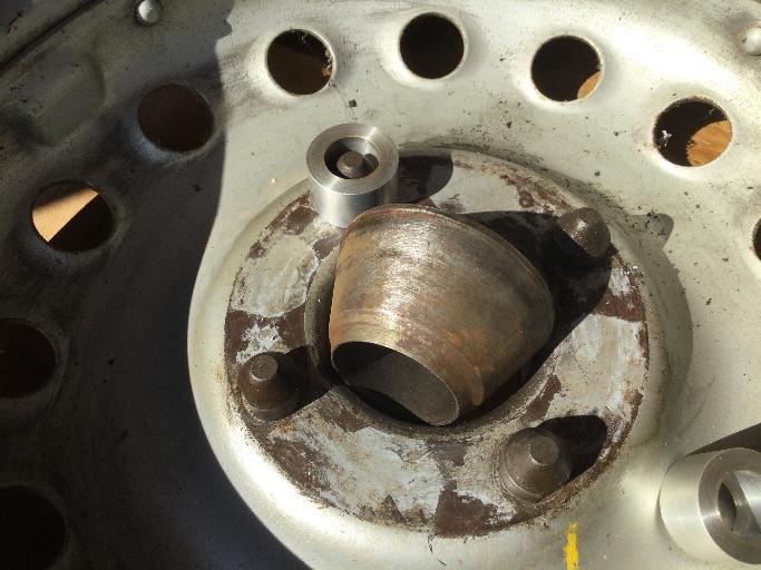
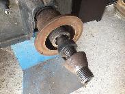
And a close-up of the two recommended adapter pieces (click for larger image).
Notice the cone chamfer on the ID of the plate to accept a spring loaded male cone on the balancer machine. Also notice the precision machined female cone on the inside of the smaller outboard adapter piece. This should match the cone angle on the Twin Cam wheel for firm clamping on the outboard side without misalignment.
Holes in the adapter plate must be accurately sized for close fit on the drive pegs to hold the wheel concentric. The center hole of the adapter plate must be fixtured to be centered on the balancing machine. Some machines have a spring loaded inboard cone to do this. Other machines have a selection of bushings to accurately fit the center hole of a wheel. For that method, there must be a close fit between the adapter plate center hole and one of the available bushings. Shaft diameter on the machine is commonly 40-mm, but they are not all the same. Therefore it is NOT advisable to make the adapter plate center hole that small. Better to make the adapter plate center hole larger and a standard size to fit some known common wheel center pilot diameter (but smaller than the wheel hub center hole).
Addendum September 19, 2021:
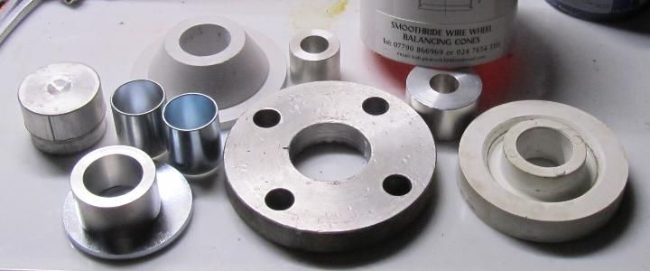
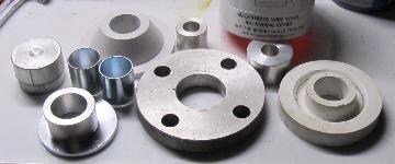
Here we have a rather extensive kit of balancing adapter parts. The piece lower right in the picture is the female cone fitting in place of the outboard knock-off nut. Other smaller parts are mostly shaft adapter bushings for various size mandrels on different balancing machines. The last picture is a 3D printed plastic drive peg spacer plate, but I have no idea why it has a cylindrical male center pilot diameter.
On 9/22/2021, Chris Champion
"The outside spacer I mentioned must have a 40mm bore so that it slides over the balancing machine arbor accurately thus insuring it will set the outside wheel face centrally to the arbor . (Most machines arbors are 40 mm diameter as standard). This spacer must be followed by the machines outside clamping device to hold everything together.
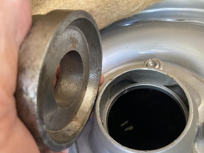
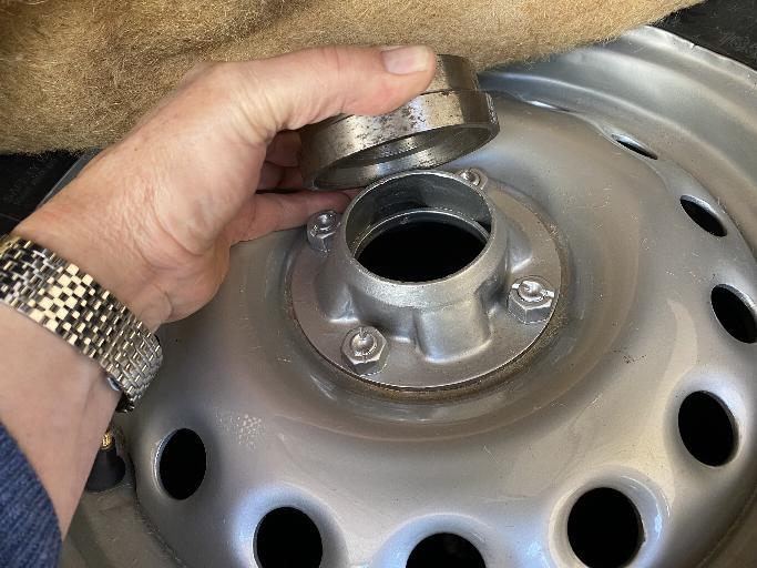
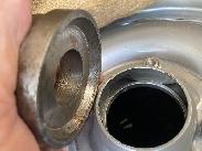
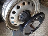
 Using an old spinner for this purpose you can get anyone with a lath to grab it by the threads and face it off and bore the 40mm bore for you. A decent machinist will know what to do if he knows that the beveled portion of the spinner must be concentric. I have included pictures to show how the spacer fits in the rim. Using an old spinner for this purpose you can get anyone with a lath to grab it by the threads and face it off and bore the 40mm bore for you. A decent machinist will know what to do if he knows that the beveled portion of the spinner must be concentric. I have included pictures to show how the spacer fits in the rim.
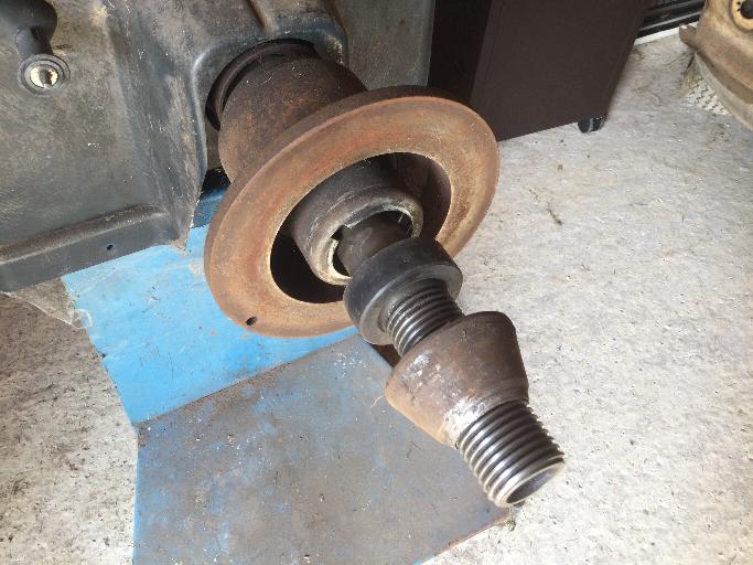
If you have available a spin balancing machine with the following standard features, the single adapter plate may be all you need. Place the adapter plate on the wheel pegs, and put the wheel on the machine. This machine has a spring loaded center cone that will pick up the adapter plate center hole to center the wheel properly on the machine. The large bell shape outer fixture will clamp down on the stud circle of the peg drive wheel, same as it will clamp a bolt-on steel wheel. With the adapter plate centered on the spring cone and held firmly against the flat face, it should work correctly for spin balancing. (Photos compliments of Jonathan Tucker)

I would not trust this to work without the special adapter plate, because the four wheel pegs may not be all exactly the same length in assembly. With no adapter plate, and irregular length pegs, the wheel would be out of plane on the machine, and maybe also not perfectly concentric at the wheel center hole.
Addendum September 29, 2021:
Another note offered by John Hopwood
"Having spoken to two professional car preparers in the historic racing world who have balanced many 100s of wheels for D Type and E type Jaguars which use the same Dunlop wheel system, they both said they use a cone that is a close fit on the wheel balancer shaft and locates against the taper in the centre of the wheel plus an external cone that is a close fit on the balancer shaft and replicates the internal taper of a spinner . The drive pegs should not touch the balancer flange and no need for a spacer".
For this to work, one must trust that the inboard female chamfer on the wheel hub is concentric with the wheel rotational axis. I tend to believe that it is, likely having been machined in the same machining set-up as the back side face, and using the same center while drilling the peg drive holes. I just can't prove it 60 years later.
The bit that bothers me is that the wheel center hub is quite short, about 1-1/2 inches between the end cones. Being only one tenth of the wheel diameter, any small deviation of those come surfaces will throw the wheel rim off by 10X the distance, putting the rim out of plane. Food for thought.
Here is another method offered by Jonathan Tucker in th UK.
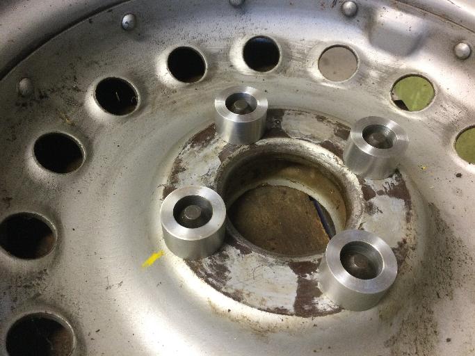
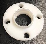
"The simple fact is that the Dunlop wheels, in theory, can go straight on the balancer with no adapters at all other than the standard centering cone. You have to accept that the central hole in the wheel inner face is concentric with the drive pegs. The one problem with this approach is that the drive pegs vary in height by quite a margin. I have turned up 4 collars to fit over the pegs all of the same size, and therefore, weight but most importantly the same length/height of about 20 mm. These hold the wheel hub face parallel with the balancer flange. The standard holding plastic cup on the machine holds everything in place and the spring loaded cone centers the wheel as it is tightened up.


Some might find it easier to knock up these simple collars rather than have the plate made up which requires more sophisticated machine work to accurately place the drive peg holes. Drive pegs appear to be 3/4 inch minus about 5 thou. Other sizes were 1-1/4-in OD and 20-mm in height to clear the pegs. I hope the photos make sense but please also refer to my original posting and Barney's kind replication of my photos. Material used was aluminum for ease of machining and lightness".
|