The MGA With An Attitude
MGA WINDSCREEN TECH DAY -- WT-102
January 26, 2002 - Naperville, Illinois
Hosted for members and friends of Chicagoland MG Club
Photos and web page courtesy of Barney Gaylord
Click on small images for larger images.- Larger pics average 30KB.

|
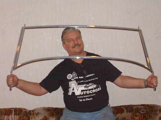
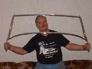
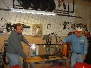
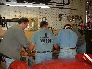
The object of the day was to get this thing assembled and installed on the car. This had been done before, just a few years earlier while installing new glass, but the (cheap) chrome plating job done at that time was bleeding copper stains from the brass base metal to the surface. So this time a spare windscreen frame was processed through a local Harley Davidson motorcycle shop to their favorite vendor for chrome plating. For the Harley crowd good chrome is next to godliness, so this time the finished plating is absolutely astounding.
|
 |
 |
 |
 |
|
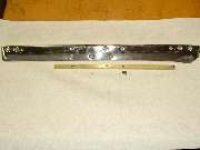
The new windscreen frame was plated and preassembled well in advance of installation day to be sure everything would fit properly. And good that it was, because there are often some problems with the bits and brackets that hold it all together. The original brackets and screws for instance had 2BA standard threads with noticeably small screw heads and pitch of about 30 threads per inch. Replacement brackets and screws installed in the late 80's had SAE or UNF standard #10-32 (32 threads per inch). If you chase a 10-32 tap through the old brackets you can use 10-32 screws, but there's no way you can use the 10-32 brackets with the 2BA screws. Some additional hardware problems are noted below. Most new brackets and screws supplied now should have the original type 2BA threads, but it bears checking both your existing parts and the new parts to be sure they will match.
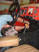
Removing the old windscreen from the car was actually fairly easy. Half of the time here was consumed removing about 30 small screws that retain the interior kick panels in front of the doors. After that just two bolts on each side holding the windscreen side posts to the body of the car, and three small screws on each side that attach the grab handles to the posts, and the whole windscreen assembly lifts out. Then only about 10 minutes was needed to remove 4 screws each side for the side posts, and 4 smaller screws each side for the corner brackets, and the frame pieces were easily pulled away from the glass. And take a few minutes to clean the glass before beginning reassembly. Keep in mind that this one was easy because it was assembled with all new hardware just a few years earlier. If you have to disassemble an original 40 year old windscreen, at least you can expect to break some of the brass screws, and you had best plan on buying all new brackets and a proper screw kit.
|
 |
 |
 |
 |
|
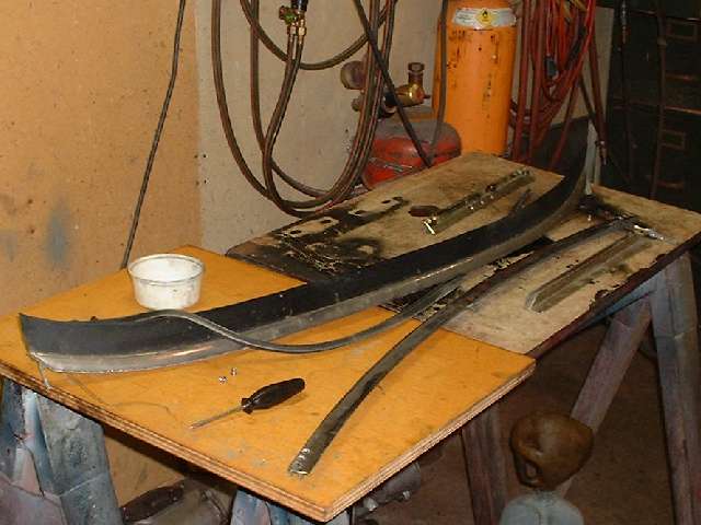
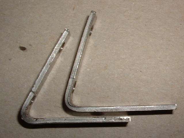
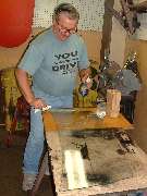
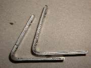
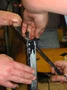
Now picture some of the small brackets that give most of the problems. At the left above are the bottom corner brackets. The one with the more acute bend has the correct angle, while the other piece is as it was received from Moss Motors. This was not difficult to reform, just a bit tricky getting the angle right, which required a couple passes at trial assembly. I later procured another pair of these brackets from Clarke Spares and Restorations. Those parts were a little shy on the bend angle as well, but much closer to being right than the Moss parts.
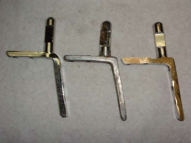
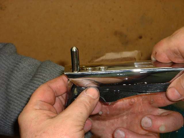
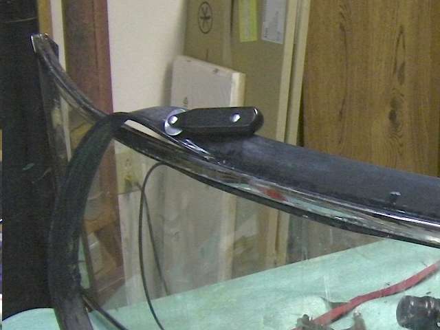
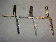
Next we have the top corner brackets, two required, with the parts shown here being from the right hand side. The part in the center is an original bracket as installed on the car from the factory. It is a 100% brass casting with chrome plating. The part on the right came from Moss Motors in November 2001, and from my experience it is the same part they have been supplying for several years. It is a 100% brass casting with chrome plating as original, but unfortunately it didn't fit. The angled part of the bracket was too thick to fit into the slots in the windscreen frame parts, and it required considerable grinding on both sides to thin it down enough to fit. This was not just interference caused by the thickness of plating, but substantially more. I had to reduce the thickness of the part by about .015 inch before it would fit into the mating slots. Then some of the threaded holes were far enough out of position that the screws could not be installed without enlarging the holes in the frame. This is generally unacceptable for a couple of reasons, the first being obvious damage to the chrome plating on the frame. The two top screws are grommet head screws, and two of the side screws are flat head screws, all of which fit into countersunk holes in the frame. When these are misaligned the screw heads will not seat fully down into the holes and may remain standing proud of the surface. Additionally, the top post on this bracket is fixed at the wrong angle. Where it should be perpendicular to the top leg of the bracket it is actually parallel to the side leg. As such, when in final assembly the two posts are not parallel but are canted inward at the top. If the mating bushings in the convertible top front bow have sufficient clearance this might actually work, but by this time I wasn't bold enough to pursue it any farther. After some discussion with Moss Motors they said many people had used these parts successfully for some years, but if I wasn't satisfied they would take the parts back for a full refund. I decided to keep these parts for my personal novelty collection. The part on the left came from Clarke Spares and Restorations, designed by and special made for Todd Clarke. The angle part of this bracket is made from rectangular steel strip stock, bent and drilled and tapped. The top post is a brass screw machine part with a reduced diameter pin at the bottom which is staked (riveted) into the steel bracket, and the part is then chrome plated. This is a very strong bracket, and a very good fit, and it dropped right in on the first try. I am very happy to have found these parts, and they are now installed on my car.
Addendum, June 2013:
On 05 June 2013, Art Pearse in Ontario, Canada wrote:
"Not only is the screw set wrong, but the holes in the upper corner brackets are off compared to the frame and the screws won't all enter, unless I deface the frame. The pegs on the top brackets are still parallel to the sides, not 'upright'. Also the Moss brackets are are too big to fit into the top bar (~.003)".
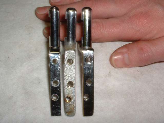
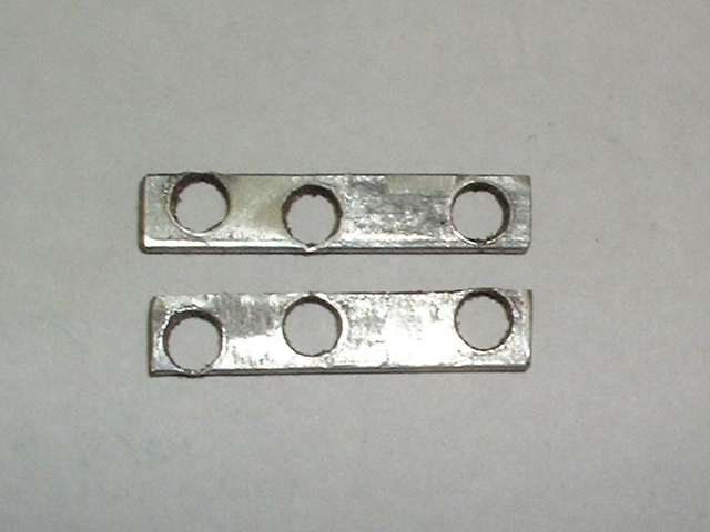
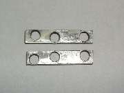
 The last picture on the far right above shows a pair of 1/8 inch thick steel spacers that I made to help with the preassembly. The top corner brackets fit with a small gap between the side leg and the inside of the frame of the windscreen. I presume this is intentional, so that in final assembly the screws will pull the frame pieces tightly together at the mitered corner joint without leaving a gap. It all works quite well without these spacers at final assembly, but it was convenient to have them installed while trial fitting without the glass there to hold the parts in correct alignment. Photo at right shows the test assembly without the spacers and the side rail pulled in too far. It also shows the Moss Motors top corner bracket with the top post at the wrong angle (should be straight up).
|
 |
 |
 |
 |
|
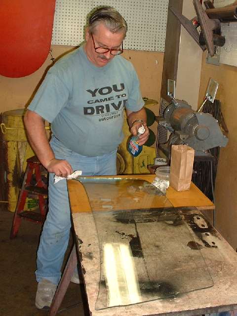
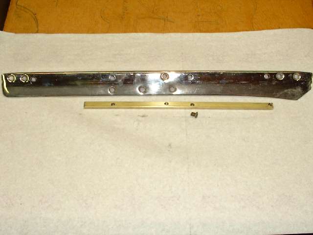
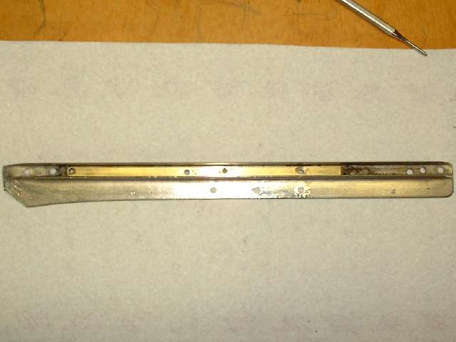
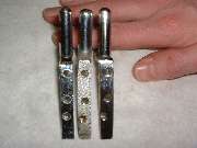
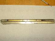
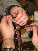
Two pictures on left above show a small brass tapping strip that is held in place in the windscreen side frame by one flat head screw. This strip provides the anchor threads for three of the four screws used to secure the side mounting post. The top screw in the mounting post threads into the bottom hole in the top corner bracket. Here there was apparently a change of tooling somewhere in mid production of the MGA model, such that there can be a slight misalignment of the screws which may require enlargement of one or two of the holes in the side frame. This is a very small change and does not materially affect assembly of the countersunk screws in the side post. Notes in the previous few paragraphs are the reasons why it is necessary (or at least desirable) to preassemble the entire windscreen frame before attempting to install the glass. Having done all this in advance, today's installation was relatively trouble free.
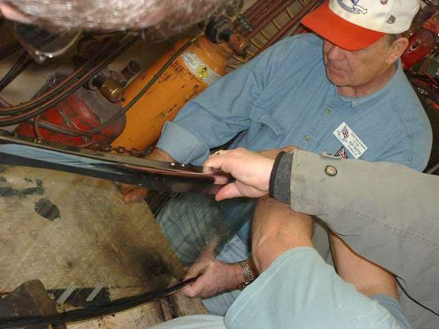
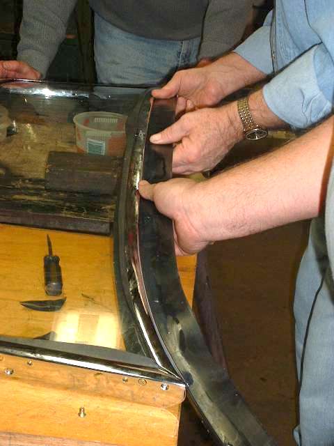
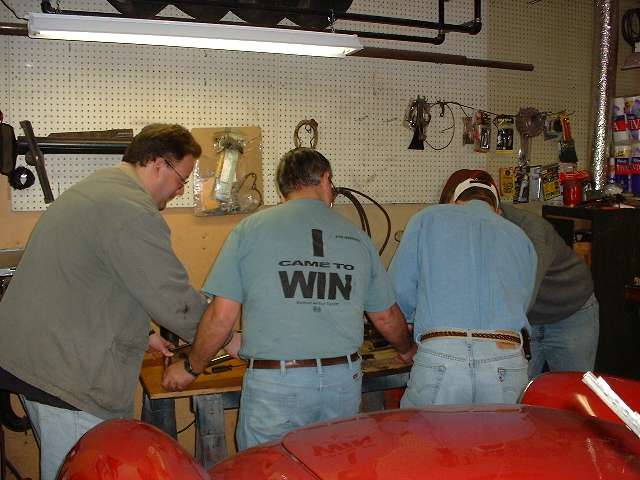
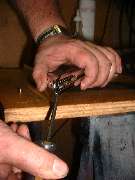
The next part of the job is one of those things that can be done solo if you have the patience of a saint, but it goes a lot easier if you have some extra hands to help you hold things. We started with the glass inverted and installed the bottom frame piece first. The bottom corner brackets are attached to the bottom frame in advance, and this sub assembly is then installed over the edge of the glass. There is a thin foam rubber packing strip to install between the glass and the frame. Assuming the glass is the proper thickness this packing strip can be a fairly tight fit, such that is may be quite difficult to push the frame piece into place. The easy solution here is to wet the rubber strip with a solution of liquid dish washing detergent in water. A teaspoon of soap to a half cup of water makes a nice slippery film. The parts will then slide together with very little force, and the installed frame rail can even be slid endwise a bit after installation if necessary. Try not to stretch the rubber strip lengthwise, as this could lead to shrinking later that would leave a gap in the seal at the ends.
|
 |
 |
 |
 |
|
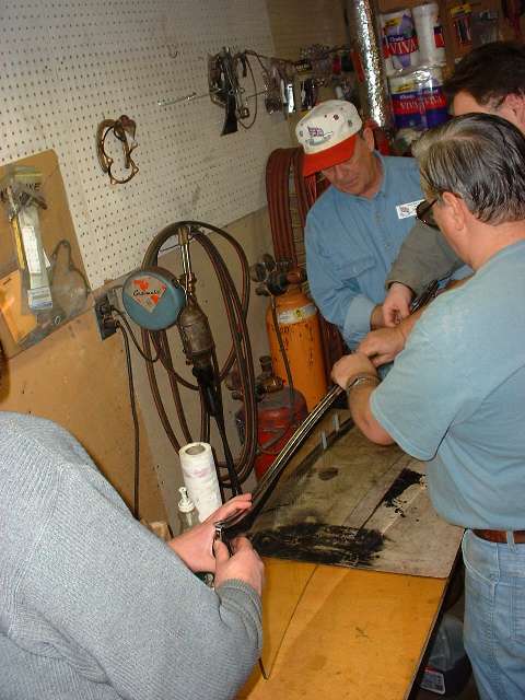
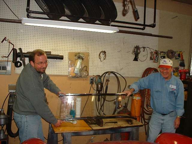
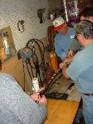
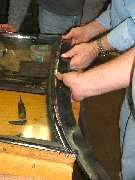
We then turned the glass upright and proceeded to install the top frame rail. A finish cut 2x4 board standing on edge makes a nice 3-1/2 inch block to support the center of the bottom frame so it will readily stand up straight. As with the bottom, the top corner brackets are attached to the top frame first, and the assembly is then installed on the edge of the glass. A little more soapy water on the rubber strip and the top frame goes on easily. A trick to keep in mind here is to keep the rubber strip centered over the edge of the glass so that when the frame is pushed into place there is about equal amounts of the rubber strip on each side. The excess rubber will be trimmed off later, but it must at least fill the entire space inside of the frame. With bottom and top frame rails in place I can relax for a minute while I leave two other guys holding the works. Before installing the side rail it's time to trim the top and bottom rubber strips back at the ends so they don't interfere.

Addendum 4 Apr 2008
Mike Addy wrote:
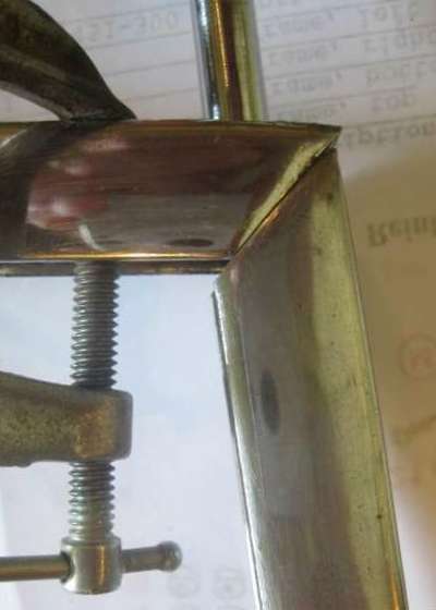
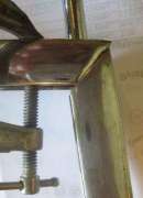
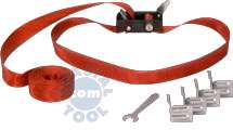
"I was working alone; a pair of band clamps was invaluable in holding the top and bottom frames snugly against the glass while I installed the side frame sections. Here's a photo of the type of clamp I used. Maybe it is called a 'strap' or 'web' clamp, but I knew it as a 'band' clamp."
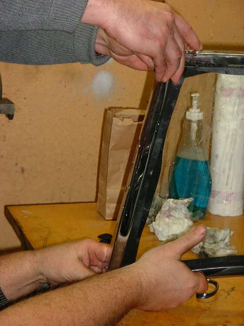
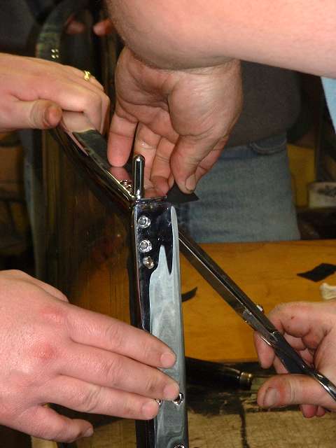
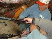
The side frame pieces are installed in a similar manner. The tapping strip is installed inside of the frame first (just one screw), then cut a strip of packing rubber with a little extra length, soak it in slippery stuff, lay it over the edge of the glass and press the frame side frame rail into place.
|
 |
 |
 |
 |
|
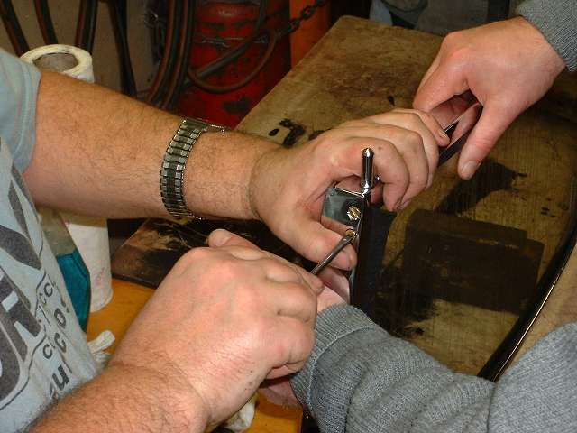
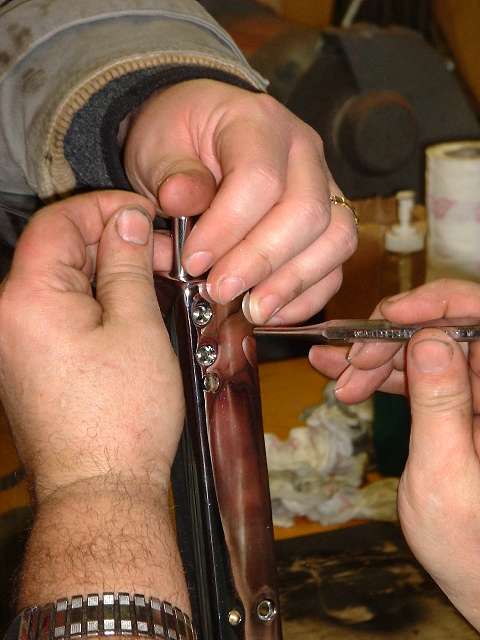
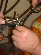
Install the screws loosely into the corner brackets. Then trim the ends of the rubber strip at an angle to match the corner miter of the frame so the rubber will not be trapped in the miter joint, and you can proceed to tighten the screws. It may help to have a small alignment punch handy to nudge the encased bracket into place while getting the screws started. The first two screws from the top are countersunk and serve to align the bracket to the third hole, which will later accept the top screw for the side mounting post.
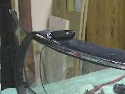
Next step is to install the bottom rubber seal strip. This is a wide rubber part with a "T" shape mounded into the top edge. It is relatively thick at the top "T" edge and tapers to be much thinner towards the bottom edge. The "T" shaped edge will slide into a slot in the bottom of the frame, but for this you have to open up one corner of the frame slightly. Loosen or remove the two screws on the side at one bottom corner. Pry the corner of the frame apart about 1/8 inch, which will be enough to allow the rubber strip to be inserted into the slot in the bottom frame rail.
|
 |
 |
 |
 |
|
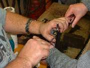
You can wet the rubber "T" seal with slippery stuff again, and just like the thin packing strips it will slide right into place. When your fingers are slippery and the strip drags a bit it can help to have some extra hands again to tug evenly along the length to keep it moving. Note that this rubber strip has an angle on the "T" at the top edge, so the flap should extend forwards from the bottom of the frame, where it will ultimately lie on top of the body cowling extending forward from the base of the windscreen. Once this bottom rubber seal is in place you can close the corner of the frame and reinstall the screws. Then it's just four screws to attach each of the side mounting posts, and YAHOO, we have a complete windscreen assembly ready for installation on the car.
ADDENDUM:
On 7/14/2011, Frank in Western Canada wrote:
"I was assembling my windscreen. Things had gone pretty well, but then I came to the screen to body seal. It was either the thickness of the chrome or the rubber strip, but there was no way it was going to slide right into place. I used pliers and water pump pliers and welding vice grips and I got within three inches of the end before it got to be too late at night and I got too tired.
I mentioned my tale of woe to a friend in my club and he said, "It sounds like my Lotus seal, I just stick one side in and then pry the other side in with a screwdriver". Knowing that works, as a few times in my pull session the bead had popped out as it was pulled along and I worked it back in with a screwdriver, I got a fresh batch of soapy water and went to get the screwdriver. In the tool drawer was a tool for putting in the spline that holds a screen door screen in place. Better idea?
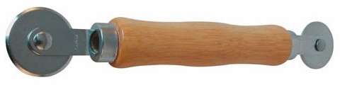
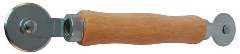 Got the tool, basically a handle with a metal wheel on the bottom and gave it a try. Zoom, five minutes and I was three quarters done. Slide in the one side, put slippery stuff on and start rolling and the T strip rolled right into place. Bit of a struggle coming out over the side of the screen at the end, and I did resort to the screwdriver there to pry it into place, but over all it was so easy I just had to pass it along".
Given enough time, it is advantageous to allow the soapy water film to dry before trying to trim the excess from the thin foam rubber packing piece between the glass and the frame. When the parts are still wet the rubber can easily be pulled out of the joint, and it's not easy to get it back in there. More notes on the trimming process later.
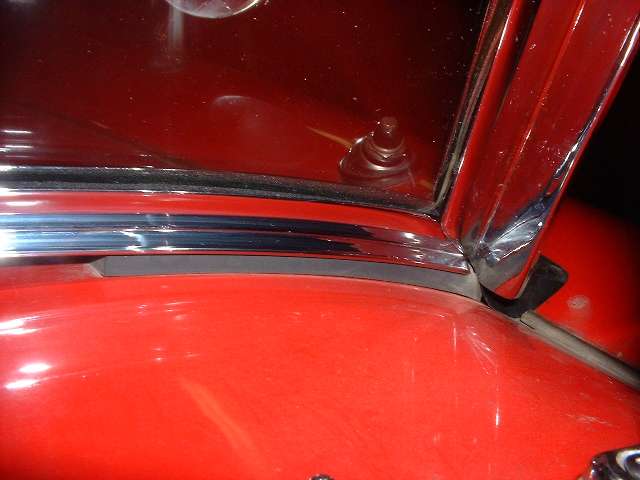
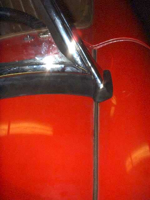
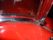
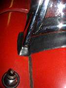
Not easy to see, but directly under my hands in this last picture above there are two 5 inch long foam rubber packing strips on top of the painted body of the car. These are placed under the bottom frame rail and as near as possible to the inside surface of the mounting post. The purpose of these rubber strips is to inhibit the entry of rain water or wind under the corner of the frame. The outer end of these strips may even be positioned on top of the rubber grommet that surrounds the base of the mounting post. The first picture below is a close up of this packing from inside the car after installation.
ADDENDUM 3/7/2014:
Someone asked about the space under the windscreen frame, so here's the skinny. Near the side posts it is about 5/16" to 3/8". From there it gets progressively larger growing to about 1/2" - 9/16" at the center. It is not necessarily the same on all cars, and it can vary quite a lot. The bottom rubber seal extends forward about 1-1/2" to lie on top of the body cowling. Aside from the rubber seals near the sides, the rest of the space under the full length of the frame is left open. Sitting inside the car you can look under the windscreen to see the wide rubber bottom seal that extends forward.
|
 |
 |
 |
 |
|
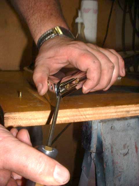
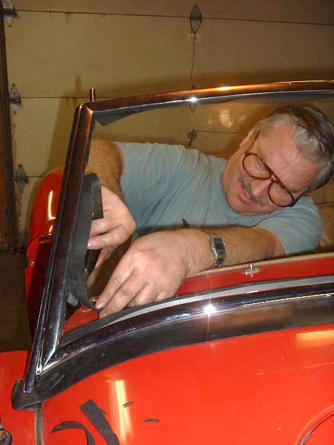
Time to drop the assembly into the body and install those four bolts in the sidewall under the dash. Here the book calls for some thin fiber packing pieces to be installed between the side posts and the body of the car to take up all of the open gap there so that the posts are not stressed when the bolts are tightened. The quantity of shims is "as required" and could be anything from zero to two on each side, depending on the configuration of the welded body shell. In this case the side posts are a tight fit to the body without using any shims, which makes life a little easier. If you do need shims here it looks like it would be easiest to glue them to the OUTSIDE of the post first, insert the posts with shims attached into the body, install the mounting bolts loosely.
On 7/18/2013, Steve Miller wrote:
"When my helper and I put the assembled windscreen in place, it had the two boots in place, so I did not really look at the gaps to the body. We tried to move the assembly back and forth, and found no play, so I assumed it did not need packing. ... Wrong answer. As I disassembled the pillars from the frame, I found that the pillars were tight on the insides of the body slot instead of the outside as they should be. So each side needed about 1/8 inch of packing, after which everything lined up properly, and did not pull the pillar from the frame. When the windscreen is put into place, care must be exercised to look at the gaps without the boots in place, so it is clearly visible".
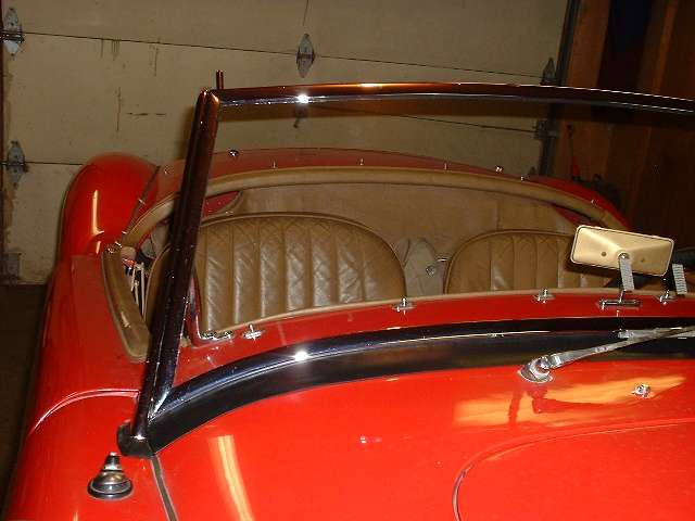
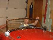
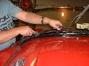
Finally install the screws to attach the grab handles, tighten everything up, and take a minute out for another big grin. Then we have a few pictures dealing with trimming of the rubber bits, starting with the last picture above and continuing below.
|
 |
 |
 |
 |
|
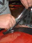
As noted before (but bearing repeating), it's a good idea to allow the slippery juice to dry before cutting or tugging on the rubber packing pieces. That said, the trimming is quite easy as long as you use a very sharp razor knife. I use a tool with a wooden handle that holds a single edge razor blade, and I reverse or change the blade every couple of minutes. When the cutting corner of the blade starts to dull it will drag and pull on the soft rubber packing strip, which is not a very tight fit in the slot. Always hold the rubber material behind the cutting edge, tension it slightly in a direction away from the cutter nearly in line with the channel, and never pull the rubber laterally away from the slot, as that would definitely pull the packing piece out of the joint. For the record, the front side of the windscreen is easy to trim, but the rear side could be somewhat easier to reach if it was done while the assembly was still on the workbench.
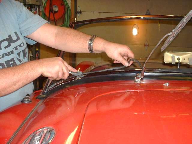
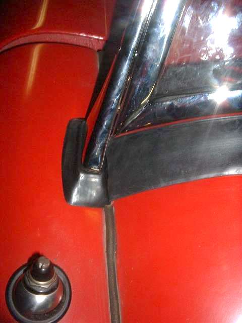
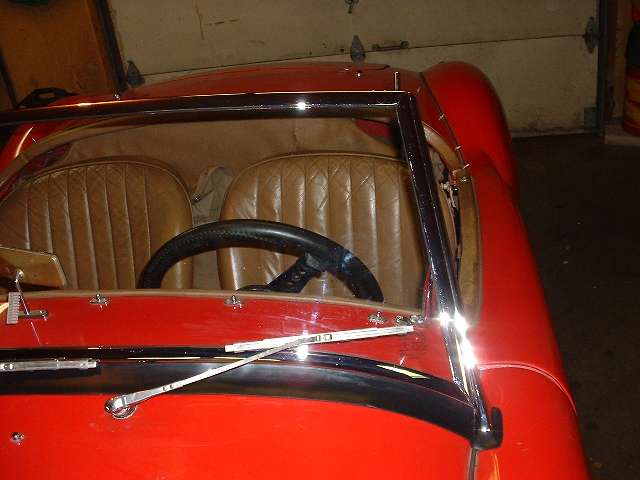
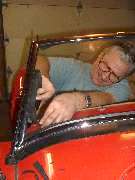
Another small chore requiring a bit of finesse is getting the bottom seal strip to lay out flat on top of the body cowling, especially at the ends. This rubber strip was stored and shipped in a flattened roll wrapped with tape, so it started out with a lot of kinks. I opened it up and hung it over a towel bar above a hot air register in the house for several days prior to installation so it had a chance to relax and get the kinks out. As a final step at installation I used a large scissors to trim the pointed end of the strip near the side post so that it drops down along the grommet at the bottom of the post to lie against the painted body cowling. Start by pulling the end of the rubber strip up tight against the inside of the post. Then position the tips of the scissors at the inside front corner of the post, and the handles of the scissors straight forward above the fender to body joint, and then clip off the end of the bottom rubber seal. When in doubt, take small cuts. It's easy to clip more off later, but not easy to put it back on if you goof. The last two pictures above show the desired final result.
|
 |
 |
 |
 |
|
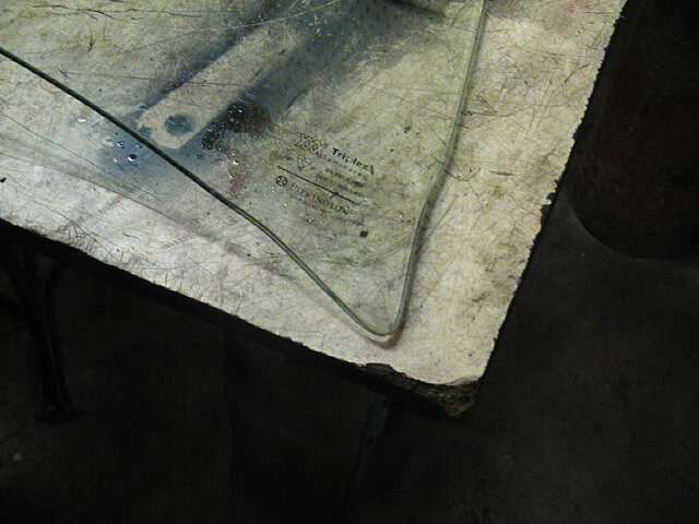
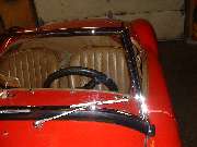
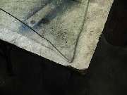
Now the trimming is all finished and it's time to show off a bit. Windex and a soft cloth or paper towel does a nice job of cleaning off the soap and finger prints, and even cleans the mold release agent off of the bottom rubber seal strip. I'm so happy with the results, and this new chrome would do the Harley guys proud. Those two white strips in the center of the glass near the dash mirror are plastic super Velcro strips for attaching the tollway I-Pass transponder box. The last picture here is the glass manufacturer's standard certification stamp, located in the lower corner of the glass. TRIPLEX laminated glass meets the USA safety standard. The lettering bears the US Department Of Transportation safety standard designation. PILKINGTON is the manufacturer's name.
For the record, this glass was purchased from Moss Motors, Ltd in January 1998, and I do not know if they are still supplying glass from the same source. Friends have recently been relating some nasty details about new MGA windscreen glass (from different sources) which is definitely not the same as this one. I did some careful measurements of the slot width in the windscreen frame, and the free thickness of the foam rubber packing strip, and the thickness of the glass all around the edges. Some new glass is as thin as 3/16 inch (0.187"), where this one is nearly 1/4 inch thick (0.220"-0.240"). If 3/16 inch thick glass was used there would be zero compression of the soft foam rubber packing strip inside of the frame channels. This would likely allow the glass to shift around in the frame, and possible even allow the rubber packing to work its way out of the joint. For such a thin glass one might well consider using some sort of adhesive on the rubber packing strip.
 Additionally, other glass is apparently not the same size around the perimeter. All of them that I have seen in recent years have some relief of the edges for a few inches back from the corners on all sides. But they are apparently not all the same overall height. The Moss Motors MGA parts catalog has a reprint of a factory Service Memorandum in the back dated 2 July 1962. This mentions replacing the early wood packing piece inside the bottom frame rail with a newer replacement rubber packing piece. This part was used to support the original glass (which was straight all the way along the edges) so that it did not rest on the bottom corner brackets, which is known to cause a triangular break across the lower corners of the glass. The glass I have will not fit into the frame if there is any packing piece used inside the bottom rail, so it appears that the height of the glass was increased slightly along with adding the relief in the corners such that the glass is now intended to sit directly on the bottom frame rail with only the soft rubber glazing strip.
On the other hand, I have a recent report (December 2001) of installation of one of the thin glass windscreens (maker unknown at the moment) which would move vertically in the frame. When it settled to the bottom it left a gap above the glass at the top corners of the frame (where there is an edge relief in the glass) that you could slip a knife blade through. This one may have been made to the original overall height dimension, in which case it probably does need the original type support packing piece inside the bottom frame rail. But for the life of me I still don't understand why anyone makes the glass only 3/16 inch thick.
I hope you've enjoyed this tech session, and here's also hoping that this information might save some people from some of the potential pitfalls of MGA windscreen service.
Best regards, - Barney Gaylord
|
|
|