The MGA With An Attitude
TEMPERATURE SENSOR LINE - DT-101C
Installation & Routing #3
Temperature gauge capillary routing.
The capillary length is the same for both pushrod and twin cam MGAs.
Pushrod
The pathway of the capillary for the temperature gauge on the pushrod cars is on the right side of the engine. After leaving the head it is clipped to the side of the engine and passes through a 1 hole on the right of the bulkhead.
Twin cam
The temperature gauge capillary on the twin cam passes along the left of the engine bay and then capillary passes through a 1 hole in the bulkhead behind wiper motor.
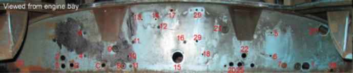
Figure 1: The capillary passes through hole #1 in picture above (image from MGA twin cam group).
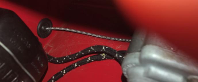
Figure 2: On the engine side (Twin Cam), the capillary passes through the bulkhead to the left of the voltage regulator (RHD) or brake master cylinder (LHD).
Fastening of the capillary in original cars is at odds with the parts described and listed in the SPL. It appears that the pushrod drawing was copied directly to the twin cam page. The SPL lists two P-clips (PCR0307) for the bulkhead, front and rear and a spring clip at the bulb end of the capillary. In the actual factory installations, the capillary is held by a single P-clip (PCR0307) on the dash side of the firewall (Fig. 3), a P-clip (PCR0507) on the upper coil mounting screw (Figs 4 & 5) and another P-clip (PCR0407) on the inner guard, fixed by the same ¼ screw that holds a P-clip for the coil wire (Fig. 6). There are some (2-3) approximately 2 diameter coils in the capillary between the inner guard P-clip and the thermostat housing (Fig. 7) that holds the sensing bulb, to prevent vibrational damage.
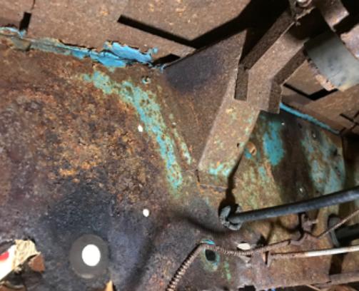
Figure 3: Dash side of bulkhead showing P-clip holding capillary. The oil pressure capillary is held by a P-clip on the same screw.
The bulkhead grommet (Fig. 2) is 1 OD and a bore size 7/32, available at https://www.autosparks.co.uk/electrical-components/grommets. It is usually installed during assembly of the gauge because of the difficulty in stretching over the sensing bulb, so if having a gauge rebuilt, make sure the rebuilder is aware that installation is required.
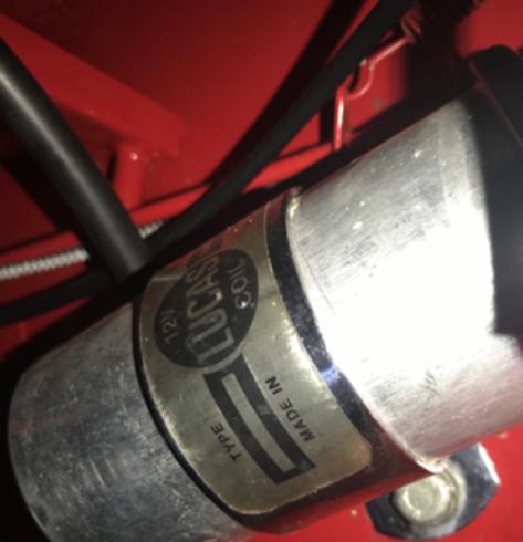
Figure 4: The capillary can be seen passing above the coil (Twin Cam) where it is held by a P-clip attached to the top coil mounting bracket screw.
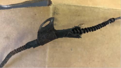
Figure 5: The original protective wrapping of the capillary can be seen where it passes through the P-clip at the coil mounting bracket. This wrap was used for all fixing P-clips.
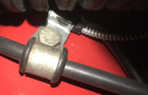
Figure 6: The capillary is fixed to the inner guard at the same place as the coil lead (Twin Cam). It is then coiled before going to the thermostat housing.
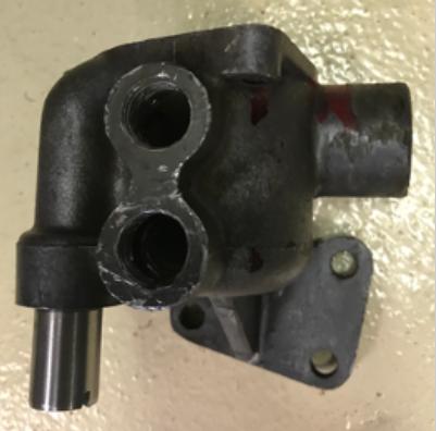
Figure 7: The sensing bulb is located in the lower of two holes in the thermostat housing (Twin Cam). The upper hole is for the heater pipe or a blanking plug if no heater is fitted.
Gauges
Temp gauges in the SPL have the same part number (17H298) for pushrod and twin cam cars but the gauges themselves seem to have a range of part numbers at the top of the faces, the difference is unclear. The most common is GD 1501/01 (Fig. 8)
So far the numbers observed (Jaeger faces with PSI oil pressure units):
GD 1501/00 early cars up to 1958
GD 1501/01 °F pushrod, and twin cam 76 capillary or 2360mm (7 8) long from back of the gauge to the tip of the sensor bulb
GD 1501/02 °F 1600 Pushrod, Australian delivery length 76
GD 1501/04 °Celsius face
GD 1501/08 °F twin cam 76 capillary
Early MGB with Smiths face:
GD 1500/18 °F
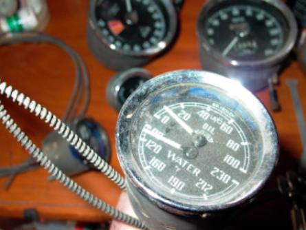
Figure 8: MGA gauge showing part number (GD 1501/01) at top of face.
|