The MGA With An Attitude
BODY FIXTURE with Twin Cam unique holes for the heater shelf - TC-270
This article is provided by John Hopwood
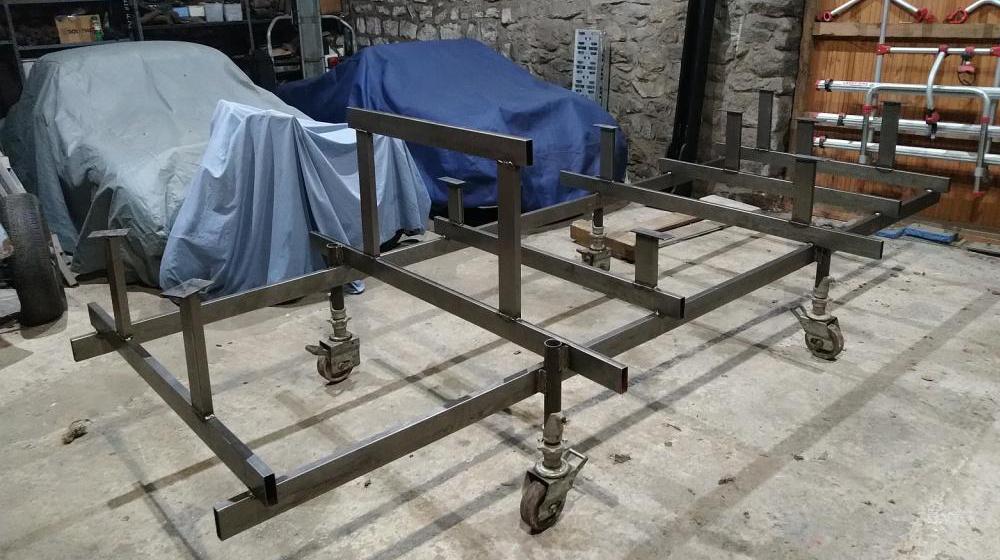
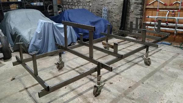
MGA body support frame
Using 25 mm x 75 mm 1.5 mm wall thickness steel tube and 50 mm x 5 mm steel strip, my cutting list was
25 x 75 steel tube
2 off 3,600 mm
2 off 1,680 mm
4 off 1,300 mm
2 off 305 mm
2 off 467 mm
2 off 264 mm
2 off 333 mm
2 off 300 mm
1 off 950 mm
50 mm x 5mm steel strip
8 off 140 mm long mm drilled 5/16 clearance hole on the centre line 25 mm from one end, weld on top of verticals with centre of hole 25 mm outside the outside face of the vertical tube, this leaves 15 mm on the inside so plenty of area to weld.
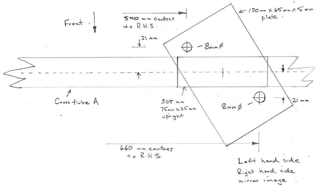
2 off 100 mm x 65 mm x 5 mm steel plate (I welded up from 2 pieces of 50 mm wide strip)
Drill after welding on top of front (A) uprights.
Spacing of the longitudinal tubes is not critical, I used 1,146 mm because that gave me the best spacing for my casters to fit on my trailer ramps.
I welded up each cross tube with its verticals and top plates, getting the lateral hole spacing right before welding each assembly to the longitudinals. Critical to set up the longitudinals parallel and level before welding the first cross tube (A) assembly onto the longitudinals. I then welded on cross tube assembly F, checking dimensions and diagonals.
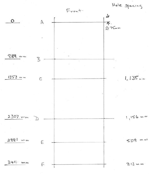
Cross tubes are identified from, front to back, dimensions are from c/l of front cross tube A and to centre line of tubes. Cross tubes B and D are the wider tubes (1,680 mm) so the ends are outside the body and can be used for rope slings, not essential.
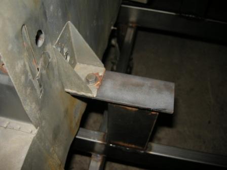
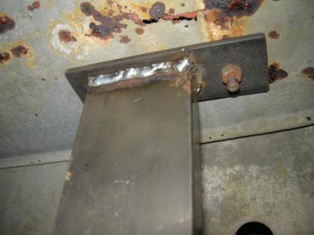
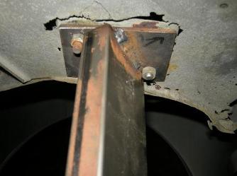
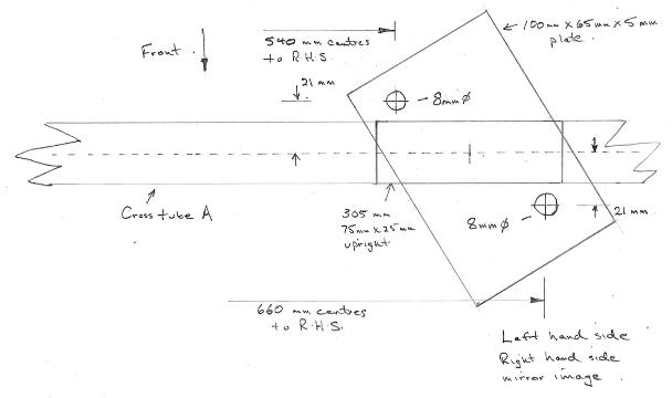
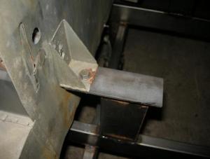
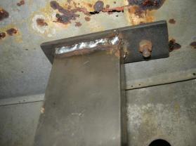
Front cross tube (A) picks up on the body mounting holes through radiator duct panel which match up to the holes in the chassis extension. Centre line of A is taken as the zero datum for longitudinal measurements. Weld A around 75 mm back from the front end of longitudinals, exact position is not critical, but all other dimensions are measured from the centre line of A. Verticals are 305 mm, separation of verticals (at centre line) is 600. Drill plates to match the chassis extension after welding to upright, plates angled out by 30 °as sketch below. Exact position is not critical, but it must be inside the outer rear corner of the upright to clear the inner wing/radiator duct panel flange, centered up is about right. This is the only fiddly one! Photograph and sketch both of left-hand mounting point.
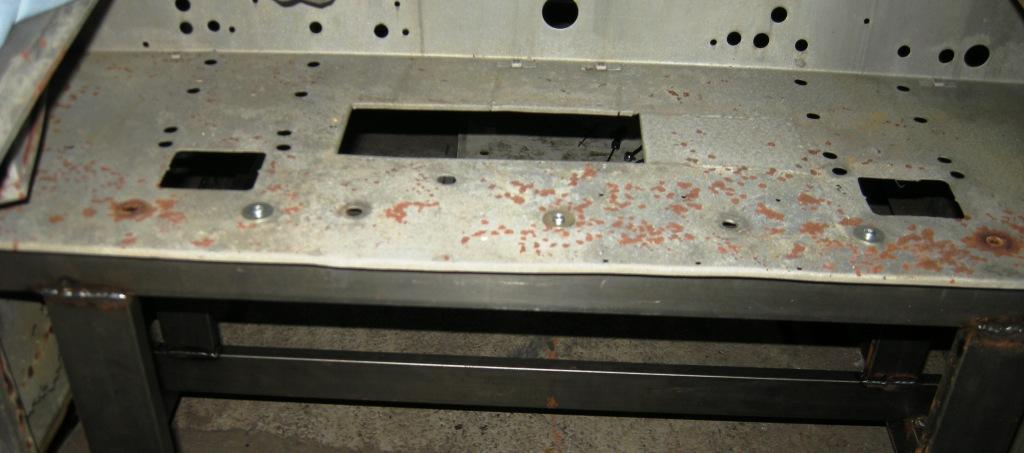
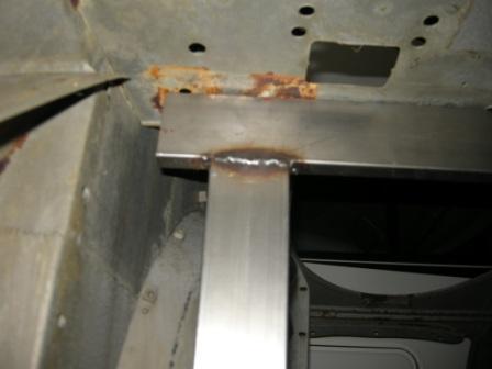
Next cross tube (B) does not have plates but has a transverse 950 mm long piece of 25 x 75 tube on top of the verticals on top of which the scuttle/heater panel sits. Verticals 467 mm, c/l of verticals 775 mm. 889 mm back from A. If you cant get 25 x 75 tube, the length of these verticals must be adjusted, if the tube you can get is more than 75 mm wide decrease the length by the extra width of the tube you get or vice versa. Similarly, if your steel strip isnt 5 mm thick, if you get thicker reduce the verticals by the difference.
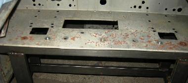

Drill through a few of the holes and fasten down with washers and large self-tapping screws. Care, the mounting holes in the heater panel are not all in a line, and holes for the Twin Cam (and "Deluxe") bodies are in different location than for the pushrod engine cars.
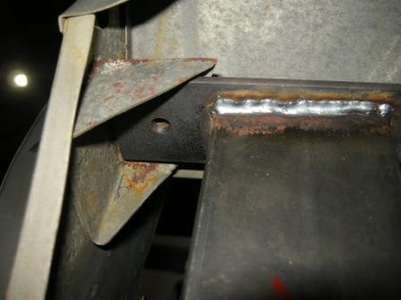
Next cross tube (C) picks up on the brackets in front of the doors, vertical tubes 175 mm, c/l of verticals 1010 mm, holes outside, c/l of holes 1,135 mm. Cross tube 1,353 mm back from A.
Next cross tube (D) picks up on the brackets where the body mounts on the brackets on the sides of the frame behind the door. Verticals 264 mm, c/l of verticals 1,032 mm, holes outside, c/l of holes 1,156 mm, cross tube 2,307 mm back from A.

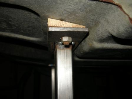
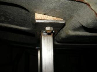
Next cross tube (E) picks up on the two mounting holes in the middle of the boot (trunk) floor, you will need to make some small wooden wedges as this panel is not level, dimensions are not on the workshop manual frame diagram, getting the steel work accurate would be difficult. Easy by making some wedges! Verticals 300 mm, c/l of verticals 383mm c/l of holes 508 mm. Cross tube 2,881 mm back.
Final cross tube (F) picks up on the rear bolt in the rear corners of the boot floor. Tubes 333 mm long, c/l of verticals 686 mm, hole c/l 813 mm. Cross tube 3,411 mm back.
I welded round tubes onto the frame to accept some old scaffolding casters so moving the whole thing round is easy, the separation of the longitudinal members was determined by the dimensions of my trailer so the casters were spaced to run straight up the ramps and onto the trailer. Flat plates for bolt on casters would work equally well. Two cross tubes are wider than the others so I can use them as lifting points, ropes outside the body line.
|