The MGA With An Attitude
Timing Chain INSTALLATION - TC-318B
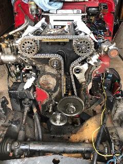 Please do refer to the Workshop Manual and Service Parts List for information on parts and installation of the Twin Cam timing chain. There are instructions for setting the crankshaft at 1/4 turn, 90 degrees from top dead center, to keep the high crown pistons away from the open valves, and special tool locking blocks to lock the camshafts in place. When all shafts are in proper position, there are instructions for indexing the cam sprockets to various holes to get the cam timing spot on. This is tricky stuff until you understand how it all works.
Refer to the prior pages for information on the chain adjuster, change of design and change of part number, and how to repair an adjuster arm that may have the thread worn or stripped. Also note there are chain guide sliders on the longer vertical run of the chain and on the top horizontal chain guide to suppress chain slap when it gets a little loose. Those pieces are lined with a hard plastic called Micarta which is riveted onto the brackets. Best to use countersunk copper rivets and copper locking washers here. Do not use steel or aluminum rivets, and do not use pop rivets.
The Workshop manual has instructions for setting the chain tensioner (adjuster) for proper clearance on the timing chain (not tension or interference). In short, it calls for tightening the adjuster until you "feel resistance", then backing it off 3/4 turn. That may work if you have a fine sense of touch and some prior experience, but otherwise it is a rather vague method open to possible error or wide tolerances.
There is a note from the prior page, but it bears repeating here.
On 8/27/2021, Dirk Van Ussel in Antwerp, BE wrote:
"I found a simpler way: The camshafts are provided with a hexagon to put a spanner on. By moving the exhaust cam left and right,the chain is put on tension and released. This enables you to feel the clearance of the tensioner's piston by putting your finger on. When You follow the instructions of the manual it is next to impossible to give the right tension as the screw can easily be overturned 1 full turn. -- Dirk
The method of fitting the timing chain damper as shown in the factory Service Parts List is unsatisfactory and should not be used. The locating nuts should not be inside the timing chain cover. Also the use of only lock washers is not recommended due to the possibility of them becoming loose due to a combination of heating/cooling cycles, engine vibration and contact of the chain with the damper. There have been instances of the locating nuts coming loose, together with the bracket, and dropping into the timing chain. Serious damage results, including a broken chain, valves hitting pistons and even possible damage to the rarely available timing gears.
In the diagram items 31, 32 and 33 are the problem.

The bolts should come from inside the timing chain cover and the nuts outside.
Also locking tab strips should be used both under the bolt heads and under the nuts. This is shown correctly with the fitting of the timing chain adjuster, items 51, 52 and 53 (Note 2 tabs item 53 are to be used). It is not sufficient to only lock the nuts as the bolt can still unwind.
If lockwire is used for the nuts it must past through both the nuts and the bolt. If only the nuts are locked the bolt can still unwind.
The diagram of the chain path as shown in the Workshop Manual shows the bolt heads inside the timing chain case. This would confirm that the bolts were fitted correctly in production and the SPL drawing is an error.
|