The MGA With An Attitude
Smiths Radiomobile INSTALLATION INSTRUCTION - AT-112B

VEHICLE: M.G.A. SPORTS
RADIO: Models 200X, 202X, 220X, 221X and 4300
INTRODUCTION
The aerial is mounted in the drive side wing.
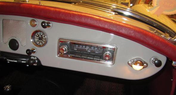
The Control Unit is mounted behind the aperture provided in the passenger side of the facia.
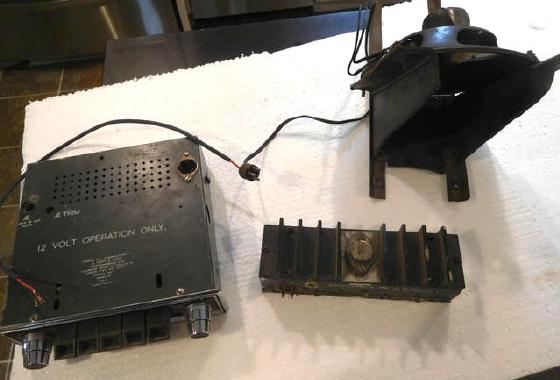
The Power Amplifier is mounted on the bulkhead behind the loud speaker location.
The Loudspeaker is mounted behind the aperture provided in the center of the facia.
AERIAL MOUNTING
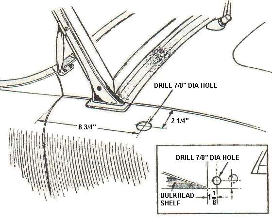
Fig. 1
Note: Turn front wheel in direction of drive side to give more working space in wheel arch.
1. Remove baffle plate inside drive side wheel arch. (Six Bolts and washers).
2. Remove trim kick panel on driver's side (Five screws and cup washers).
3. Drill a 7/8" diameter hole in wing to dimensions given in Fig.1 .
4. Drill a 7/8" diameter hole in metal panel to dimensions given in Fig. 1 (insert).
5. Fit aerial in wing.
6. Route lead through 7/8" diameter hole to inside of car and fit grommet provided.
7. Replace baffle plate in wheel arch.
8. Replace trim kick panel.
9. Route aerial lead over top of kick panel to passenger's side of car, behind facia.
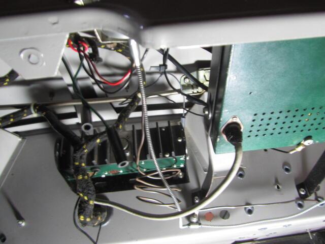
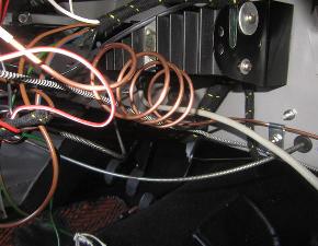
POWER AMPLIFIER MOUNTING
1. Disconnect battery.
2. Remove rubber plugs from the three holes provided in the bulkhead near centerline of car. (The location is illustrated in Fig. 2 inset).
3. Secure the Power Amplifier mounting bracket as shown in Fig 2. using the fittings provided.
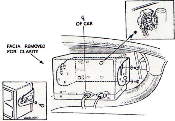

 Fig. 2 Fig. 2
4. Mount Power Amplifier in bracket using the fixings provided as shown in Fig. 2.
NOTE: When installing Model 4300 the spigots on the Power Amplifier are located in the holes and not the slots in the bracket provided.
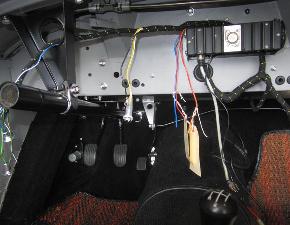
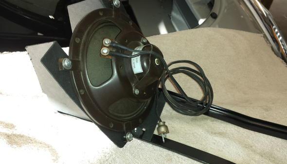
LOUDSPEAKER MOUNTING
1. Release the facia support straps from the facia by removing two screws and washers.
NOTE: When a heater is fitted in this car these screws hold the heater control panel in place -- this must be temporarily lowered away from the facia.
2. Slacken off the screws holding these straps to the bulkhead.
3. Remove the millboard blanking piece from behind the loudspeaker aperture in the facia.
4. Bend millboard loudspeaker box as shown in Fig. 3.
5. Secure loudspeaer in this box using the fittings provided.
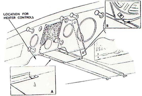
Fig. 3
Important
Ensure that the cut away flanges on the loudspeaker are at the bottom as shown in Fig. 3. (inset B.)
6. Connect lead to loudspeaker.
7. Locate the loudspeaker assembly behind the aperture in facia.
8. Locate support straps underneath the loudspeaker assembly and secure with fixings provided as shown in Fig. 3. (inset A).
Important:
Ensure that the loudspeaker mounting box is as close as possible to the back of the facia. Check that loudspeaker grill is secure.
9. Tighten these fixings.
10. Replace screws securing support straps (Replace heater control panel, where applicable).
11. Connect loudspeaker lead to Power Amplifier Unit.
CONTROL UNIT MOUNTING
1. Remove blanking plate and chrome bezel from aperture in facia. (two spring clips).
2. Retain chrome bezel (discard when installing Model 4300).
3. Models 200X, 202X, 220X and 212X. Remove knobs and escutcheon from Control Unit. See Fig. 4.
4. Model 4300 only. Remove chrome bezel from Control Unit (Four screws).
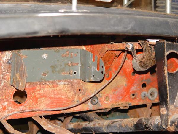
5. Remove rubber plug from bulkhead adjacent to choke cable.
Note: On left hand drive cars this will be adjacent to the starter cable.
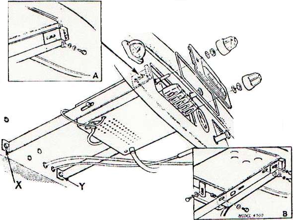
Fig. 4
6. Fit one of the support straps to bulkhead as shown in Fig. 4. using the fixings provided. (See ref. "Y" in Fig. 4.)
7. Fit the other support strap to the hole indicated as "X" in Fig. 4. (Remove rubber plug. A large washer is provided for this hole.
NOTE: It may be necessary to bend these brackets to fit set.
8. Model 4300 only. Fit the center bracket to the Control Unit (See Fig. 4. inset B.)
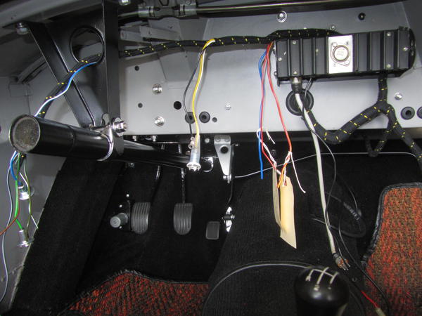
9. Mount Control Unit in support straps behind facia. Secure rear fittings (2BA x 3/8" Hex Head screws, plain and shakeproof washers).
10. Model 4300 only. Secure rear bracket to support straps (see Fig. 4. inset B). Fit the two pressure pad brackets to front springs, as shown in Fig 4 (inset A) using two 2BA x 1.8" Hex. Hd. screws, plain and shakeproof washers.

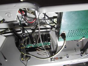
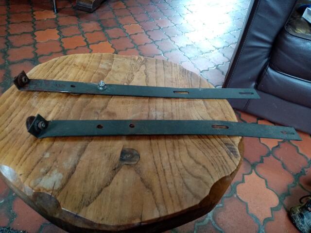
Radio Control Unit mounting brackets.loose and installed.
Brackets on left may not be original issue, possibly made of thicker material.
11. Models 200X, 202X, 220X and 212X. Fit chrome bezel behind escutcheon and replace washers and securing nuts (See Fig. 4).
12. Models 200X, 202X, 220X and 212X. Replace knobs.
13. Model 4300 only. Replace chrome bezel (Four screws).
14. Ensure that chrome bezel is located in depression in facia.
15. Adjust pressure pad bracket until facia is hard against chrome bezel -- tighten front fittings.
16. Tighten rear fittings.
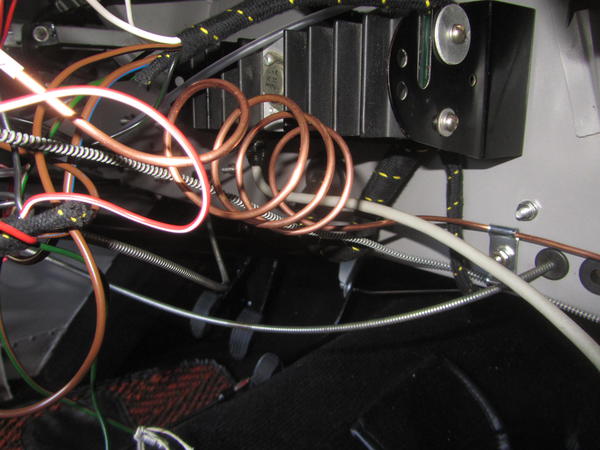
17. Connect interconnecting cable from Power Amplifier unit.
IMPORTANT: Model 4300 only. Ensure that the plug retaining screws are fitted at each end of the interconnecting cable.
18. Route battery through with main harness and connect to "A" on Control Box.
19 Reconnect battery.
Aerial Trimmer (200X, 202X, 220X, 212X)
Tune receiver to a weak signal on 12 Kc/s (250 meters) approximately and adjust aerial trimmer -- small set screw on right-hand side of Control Unit -- for maximum volume.
Aerial Trimmer (Model 4300)
Switch to "SW" band (41-90 meters) and tune receiver to a weak signal near the middle of the band. Adjust aerial trimmer -- small set screw on right-hand side of Control Unit -- for maximum volume.
SUPPRESSION
In is important to keep all wiring, i.e. ignition and capacitor leads, as short as possible and to scrape to bare metal each point at which the earth connection is made. The distributor incorporates a built-in resistor in the main H.T. lead and plug suppressors are fitted in each plug lead.
1. Fit a 1 mfd. capacitor (3/16" tag hole) to "SW" terminal on coil. Earth to coil bracket.
2. Fit a 1 mfd. capacitor (1/4" tag hole) to dynamo yellow lead. Earth to mounting bolt.
3. Fit a 1 mfd. capacitor (no tag) to terminal "A" on control box. Earth to nearest point.
4. 4300 model only. Fit a 1 mfd. capacitor to Petrol Pump. Earth to nearest point.
5. Models 200X, 202X, 220X and 212X. Fit the choke provided in the supply lead to the Control Unit at the fuse location.
Published by S. Smith & Sons (Radiomobile) Ltd., No. 2147/253. Printed in England, October 1955.
|