The MGA With An Attitude
TAIL LAMP LOCATION, 1600-MK-II -- BD-141
 Occasionally we may need to install a replacement panel for the rear body valance. Or someone may want to convert a 1500/1600 body shell to use 1600-MK-II tail lamps. Either case may result in a rear valance panel with no holes. This article may help locate the required holes for the tail lights for an MGA 16-MK-II.
 The illustration began life as a charcoal tracing taken from a 1600-MK-II car (click for larger image). So far not sure about the exact orientation, as the tracing may be rotated slightly out of position. Also the currently available image is not full scale, but we have one dimension available to rescale it to full size. We hope to have a better drawing and better hole locations later. Once the image is full size it maybe aligned with the boot lid aperture and the fuel filler hole to get correct orientation and hole positions for the right side. Left side holes will then be mirror image of the right side.
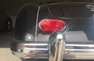
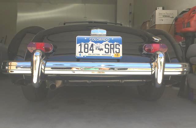
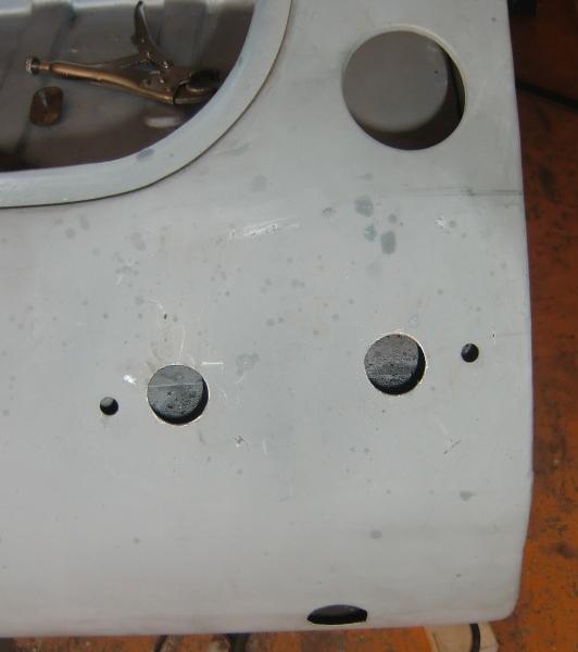
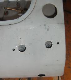
Photo above shows location of the left lamp. Bottom of the lamp fixture and plinth should be level, straight across, while top is canted downward toward the inboard end. The corner of the plinth is about an inch from the boot lid, while the outboard end is about 1/2-inch from the body edge. There are four holes in the rear valance for each tail light, one hole for each light and two holes for the bolts that hold them on. The inboard bolt hole is 7-1/2 inches from the outer edge. If you have a plinth gasket (that actually fits the plinth to body joint), you may be able to use the gasket for alignment and template to mark location of the holes.
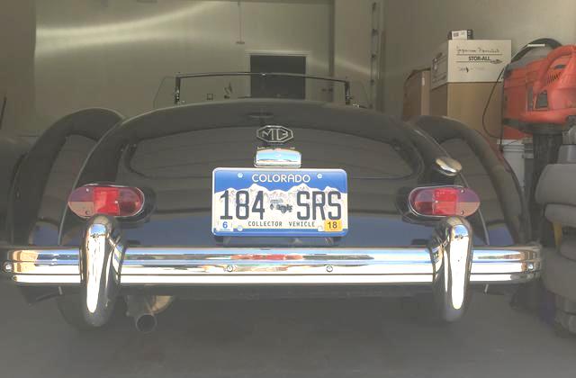
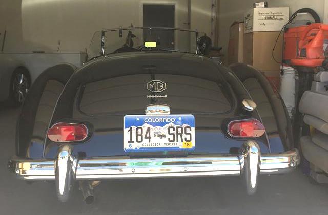
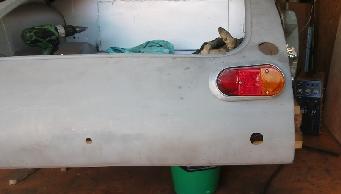
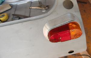
Three photos at right show the tail lamps from different elevations.
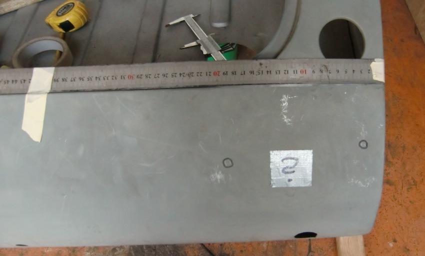
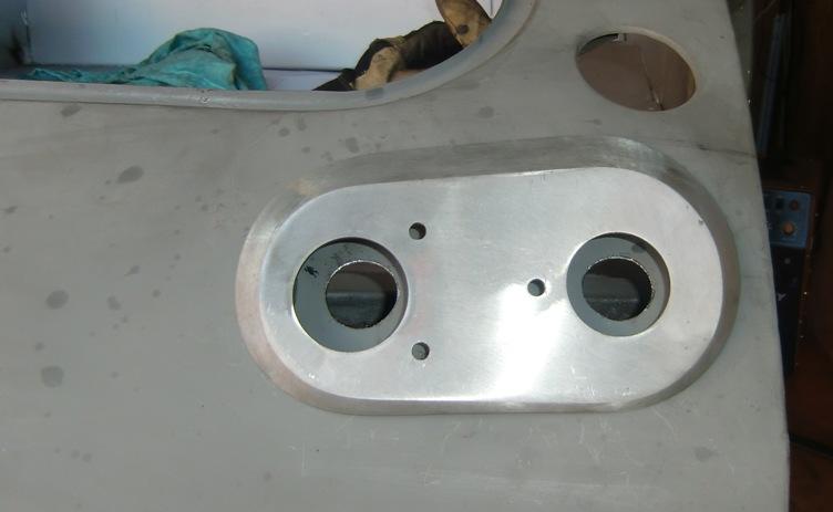
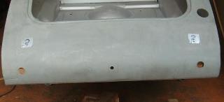
Below left is a drawing of correct hole locations for right side, dimensions in mm (click for full scale PDF image). Below right is a photo showing reference lines for the layout.
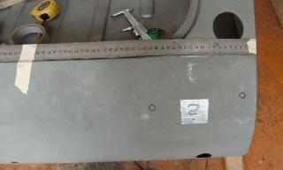
When you print the PDF pattern, measure center distance between the two small holes to assure you have the correct print scale. Then cut the template out of card stock, and try it against the lamp fixture (and plinth) before cutting the body metal.
 (Final template drawing and the gray photos are compliments of Niklas Berge). (Final template drawing and the gray photos are compliments of Niklas Berge).

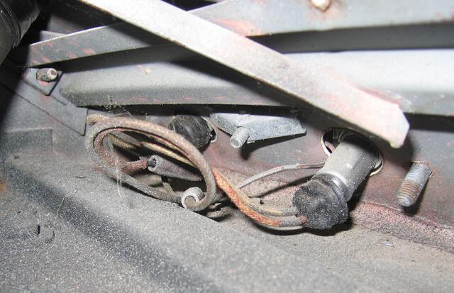
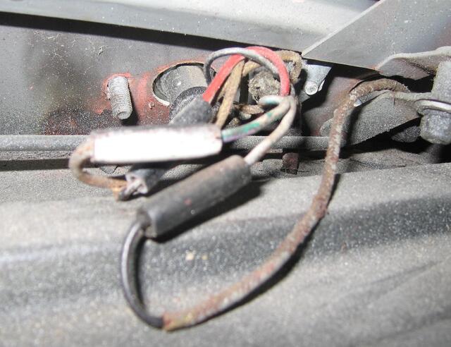
 (Wire connection photos for 1600-MK-II are compliments of Nick Kopernik). (Wire connection photos for 1600-MK-II are compliments of Nick Kopernik).
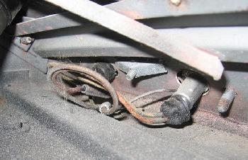
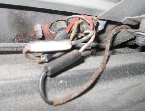
Please do not throw luggage on these wires in the rear corners of the boot space. And do be careful with placement of the wires so the boot latch release pull rods and bell crank do not rub on the left side wires. Tricky business, see the last photo, click for larger image.
|