The MGA With An Attitude
Carburetor REBUILD (for MGA) -- CB-210
Diagnostics and a short cut.
 Don't let the illustration at right get you flustered. While there are a lot of small parts here, there are only a few moving parts in the SU carburetor, so it is functionally simple and easy enough to service.
NOTE 27: Item 27 s drawn backward in this illustration. The flat side of the banjo fitting goes toward the lid, while the conterbored side goes toward the bolt head.
NOTE ALT 1: The Alt 1 banjo bolt arrangement is used on MGA 1500 cars where item 43 is a conical steel washer with conave side up. The Alt 2 banjo stud arrangement is used on MGA 1600 cars where item 47 is a flat steel washer.
NOTE 30: The "vented" fiber washer Item 30 goes below the vent banjo fitting, while the flat metal washer goes on top (along with a model number tag not illustrated).
The first lesson in carburetor rebuild is much the same as anything else. Do the diagnostic work first to see what it needs before you spend time and money fixing something it may not need. Good idea to take a few pictures before you begin disassembly.
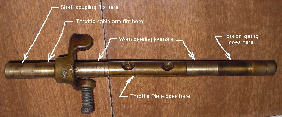
The first move will be to check for throttle shaft wear (wiggle in the bearing journals). It the engine runs you can spray carburetor cleaner (or WD-40) on the spot where the throttle shaft enters the carb body. If this makes a difference in idle speed it is good indication that the throttle shaft is worn (as the fluid stops ingress of air through the journal).
On or off the car, remove the torsion spring assembly from the free end of the throttle shaft (don't lose the small parts). If the carburetor is still in the car, remove the throttle cable return tension spring, assure that the throttle cable is slack, and loosen the shaft coupling between the two carburetors. Open the throttle valve slightly and try to wiggle the shaft in the up/down direction. Expect most wear to occur on the top side of the shaft in the rear carburetor, as the throttle cable is constantly pulling upward against resistance of the torsion spring (see photo).
If you can apply a dial indicator at this point to measure the shaft wiggle, you might avoid further disassembly or replacement of the shaft. Bearing clearance (wiggle) of 0.003" to 0.005" is acceptable and perfectly serviceable. Wiggle of 0.010" or more begs for replacement of the shaft. Clearance in the 0.005"-0,010" range is a judgment call depending on how much you might expect to drive the car in the future, state of your budget, and/or how particular you are about perfection. If you do not have a dial indicator for this measurement, beware that the clearance may be more than you might think or judge by the small wiggle. If you know the service mileage, expect the brass shaft to be well worn by 100,000 miles.
The throttle body is pot metal (aluminum and zinc alloy), and the shaft is brass. The brass is self-lubricating to some extent, but the pot metal is tougher and more abrasive, so the shaft wears faster than the throttle body. You might expect to replace the shaft twice before the throttle body bearing journals need to be drilled or bushed. If the shaft is not badly worn it doesn't need to be changed.
Addendum, July 2022: There were various arrangements of throttle shaft bushings over time. In the 30's and early 40's throttle bodies were bronze, no bushings required (but they did wear).
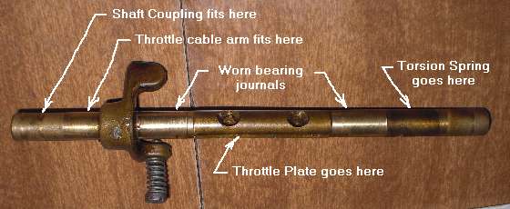
 MG T-Types and MGA (post war to early 60's) had H-Type carburetors with bronze bushings cast into pot metal throttle bodies (photo at right) and brass throttle shafts (where shafts would wear more than the throttle body). Early MGB and Midgets with HS carburetors. HS2 carbs had plain cast throttle bodies, no bushings (cheap), and brass shafts, and the shafts would wear a LOT. HS4 carbs in MGB had cast in brass bushings and brass shafts, and the bushings would wear more than the shaft. 1972-1974 MGB with HIF carburetors had a pressed in replaceable bushings, split steel sleeve with Teflon lining. The bushings didn't wear much and were replaceable, leading to long life and easy service.
If the shaft is worn enough to cause the throttle plate to drag on one side of the throat, that can cause unusual idle conditions when the throttle plate does not close properly. If it idles a little too fast, press the throttle pedal half way down and slip your foot off the side to let it pop up suddenly. This may force the throttle to the closed position for normal slow idle speed. It that works, it is further indication that the throttle plate is dragging on the side before full closure.
There is something you can do to improve that situation short of replacing the throttle shaft. You can re-center the throttle plate to avoid dragging on the wall at idle speed. This is the same procedure used for assembly of new parts. Notice the two small screws that secure the throttle plate (butterfly valve) within the slot in the shaft. The tip end of these screws is split and should be (should have been) spread out slightly wider to prevent the screws from falling out if they might happen to vibrate loose (which they should never do if properly tightened). You should pinch this split end back together a little, somewhere close to being straight but not so much as to close the slot. Then loosen the two screws about half a turn or as required to allow the throttle plate to slide around a bit in the shaft slot.
Reinstall and reset the torsion spring on the shaft to close the valve. Back off the idle adjustment screw to allow the throttle plate to go completely closed. This will put the throttle plate in contact with the wall of the throat. The idea then is to push and nudge the throttle plate as needed to position it so the entire perimeter of the plate is in contact with the wall all the way around. Look through the throat and put a bright light behind to observe any gap around the edged of the plate. When the plate is fit tight as possible to the wall all around tighten the two screws to secure the throttle plate in that position in the shaft. The throttle should then open and close freely and come to rest fully closed without sticking. Adjust the idle speed screw to be 1/2 turn open and check again to be sure the plate does not stick when shut. Finish by spreading the split ends of the screws slightly for final security.
|