The MGA With An Attitude
MACHINING THE MGA FLYWHEEL - FW-202
The MGA MK-II car in 1961-1962 had a lighter flywheel nearly identical to the early MGB. MGB uses 3 alignment pins for the clutch cover where the MGA uses 2 alignment pins. Otherwise the 1955-1964 flywheels are physically interchangeable. For street use I like the lighter flywheel (8-1/2 pounds lighter). I also like the action of the MGB pressure plate,
 especially with a slightly uprated engine.
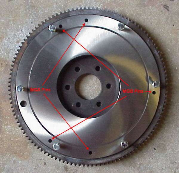
The picture and drawing here show the machining required to convert an MGA 1500-1600 specification flywheel to either MGA 1622 or early MGB specification. Dimensions are in inches. Machine out a 1/2 inch deep pocket in the front face as shown, and install the correct number of alignment pins. The flywheel will need to be balanced again after machining (or at least check the balance). Weight is reduced from about 28 pounds to about 20 pounds (plus ring gear).
NOTE: Three holes for the MGB clutch alignment pins are on the same basic circle as the MGA pins and the six bolts. Two pins for MGA are half way between the bolts, 30 degrees displacement. Three pins for MGB are displaced 7 degrees clockwise from the bolts. Calculation makes the center distance from bolt to pin 0.603 inches. One clutch cover was measured to average 0.601. The bolt holes are somewhat irregular and have sufficient clearance (about 0.040) to accommodate considerable misalignment. Bolt holes in the clutch cover may even be punched rather than drilled.
Accurate position of the alignment pins relative to each other and on the proper basic circle is important to center the clutch cover for proper balance of the assembly. Alignment holes in the clutch cover are 0.250 diameter, while the mating pins are 0.247 diameter, so there is precious little tolerance for position of the pins, not more than 0.001" radial position error allowed.
From Confidential Service Memorandum MG/267 dated 29 July 1959:
FLYWHEEL DOWELS
To facilitate removal, a 5/32" hole may be drilled from the back of the flywheel into each dowel hole. This will allow the dowels to be knocked out with a 1/8" punch.
|