The MGA With An Attitude
DOOR LATCHES and LOCKS, PHOTOS - CP-113C
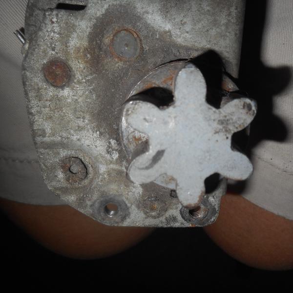
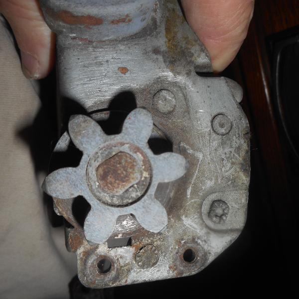
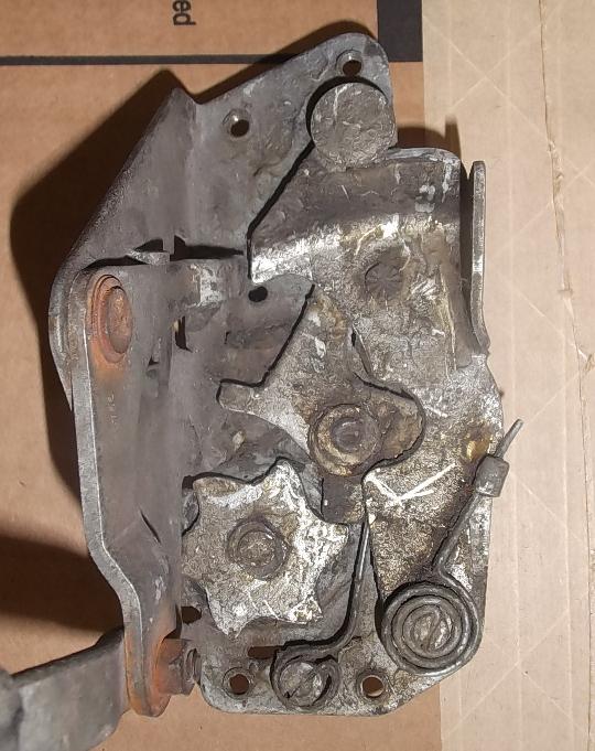
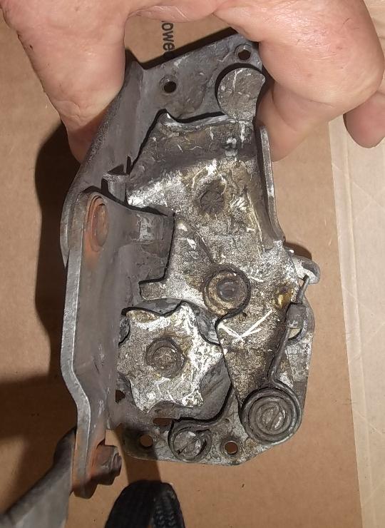
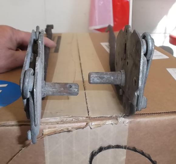
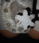
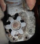
 There have been many questions about how these door latches were asembled, and how they maybe repaired. I finally conclude that the shaft holding the star wheels has two flats machined at each end making a "double-D" shape. The wheels have double-D holes and are fitted to the shaft. The double-D shapes therefore lock the wheels to the shaft, although perhaps not absolutely tight. The ends of the shaft are then peened to hold the wheels securely in place.
There may be slightly different methods to this process shown in these pictures. For the thicker gear wheel the shaft may be smashed on the end like a rivet, expanding the double-D shank to be tight inside the mating hole. For the thinner asymmetrical latching star wheel, the swaging punch may have had a hole in the center so it would smash the perimeter of the shaft, not so much the center, therefore deforming the shaft over the wheel without compressing the length or expanding the shaft inside the wheel. In either case, disassembling it would require grinding the end of the shaft flush with the side of the gear wheel, and then pressing the shaft out of the wheel. The gear wheel with the flat face may have been a repair, being welded and ground flush. Otherwise there may be an alternate method of original assembly.

On 1/28/2016, David Adams wrote:
"I do not believe that the fixing to the star wheel was originally by peening. I think it was by some form of circlip since there was the vestige of a groove in the shaft of the lock I just repaired. The double-D in the star wheel is 9/32-in across flats. Both gear and star wheels are hardened, impossible to drill. The shaft is not hardened, it is easily drilled".
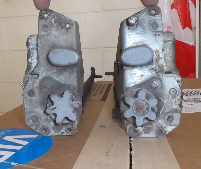
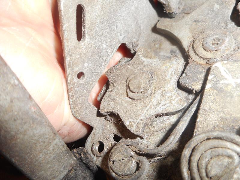
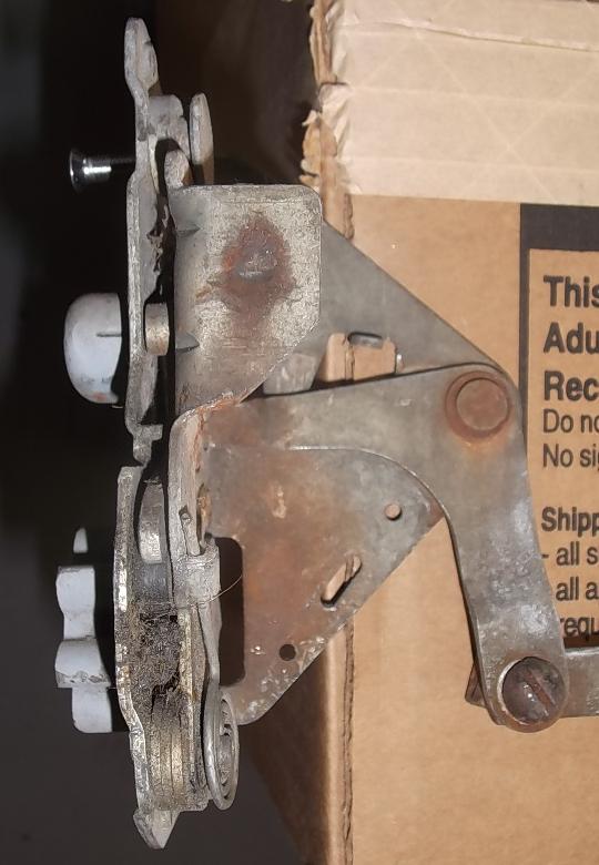
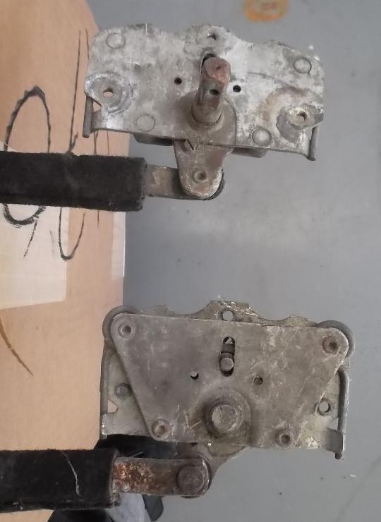
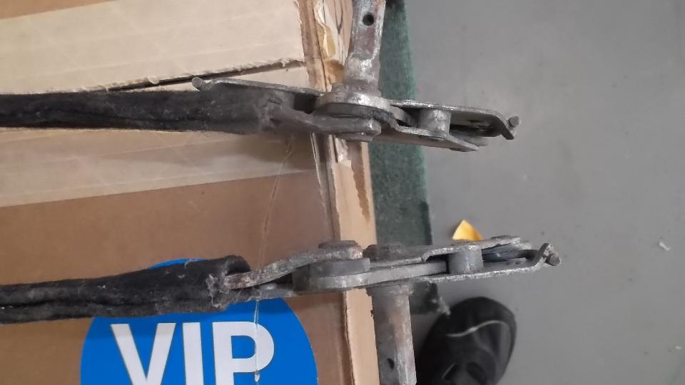
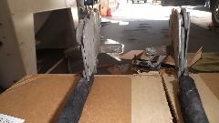
Photos below show the latching and unlatching mechanism. First left is outboard view of the right side latch, as though you were looking at it through the door skin. Second picture is inboard view of the left side latch, as though you were looking at it through the door inner shell. The next three pictures show the left side latch, looking at it front the front (inside the door). Center picture shows it all in rest position with the door latched but not locked. Next picture shows it locked from the inside (inside handle raised) with the bellcrank arm raised to block motion of the outside release arm. Far right picture shows the inside latch in normal rest position (not locked), and the outside releasing lever depressed to allow the wheels to free-wheel to open the door. Pushing the inside handle down rotates the bellcrank downward to also relese the latch. You can release this latch from inside even when locked from outside. But when locked from inside it cannot be opened from outside (not even with the key in hand).
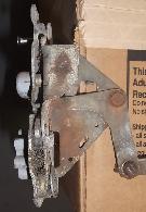
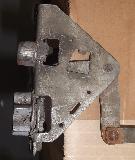
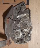
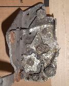
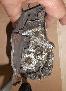
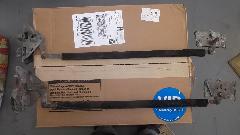
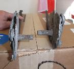
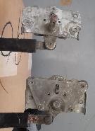 Photo at left shows inboard view of the left side interior handle crank, and outboard view of the right side interior handle crank. The top lock shows clearly a screw that will defeat function of the inside locking mechanism (left side door).
 There is no screw in the right side lock, which is shown in the locked position.
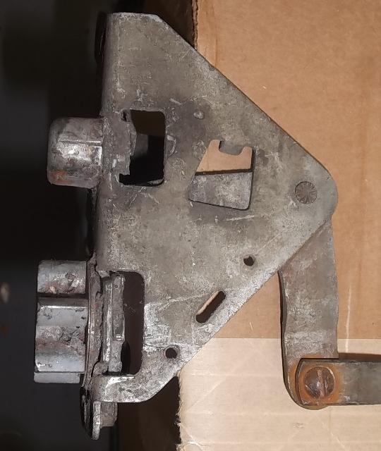
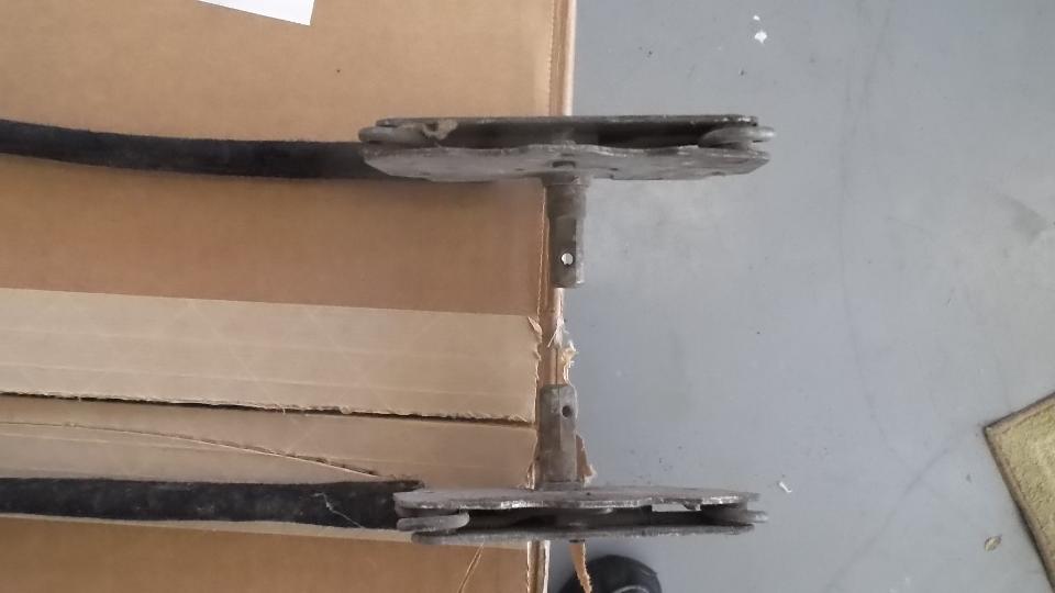
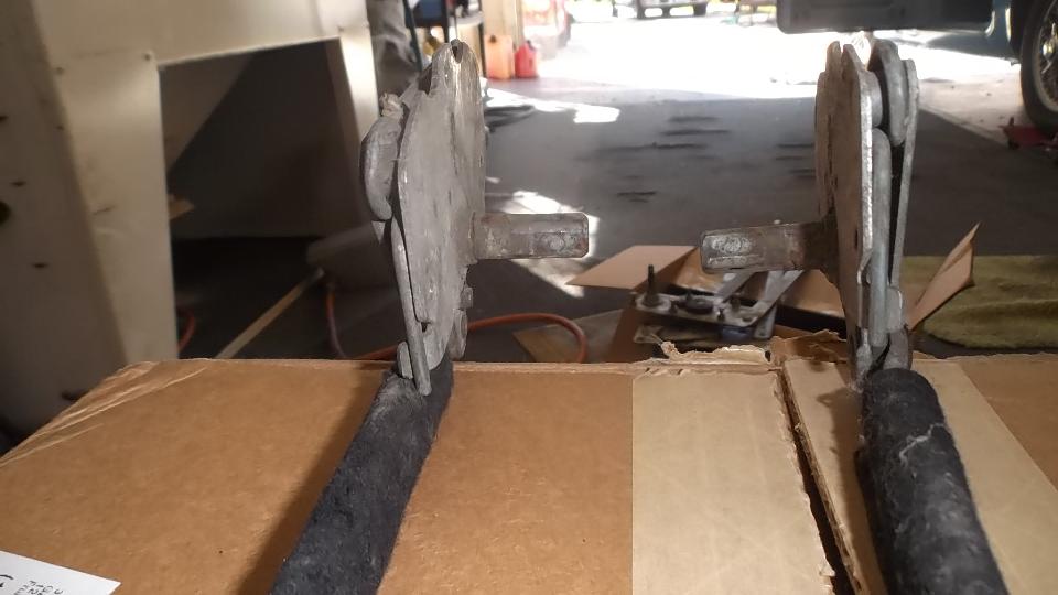
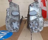
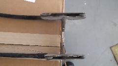
Photo at right shows both mechanisms from top. In the row below, both parts from the rear, both from the front, and both from bottom.

There is a roller at the top with stepped axles captured in a vertical slot, and held down by two springs. When the interior handle is pressed down to unlatch the door, the roller is pushed upward against the spring. The spring loaded roller then applies motivation to return the handle to horizontal rest position when released. The inside handle can be raised to locking position without moving the roller (except perhaps for a small detent) so the handle will remain raised when the door is locked from inside.
|