The MGA With An Attitude
DISASSEMBLING The SPEEDOMETER - ST-200
At 01:16 PM 11/23/2006 -0700, Colin Parkinson wrote:
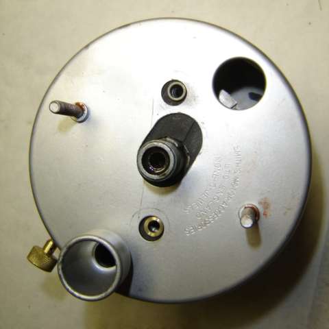
" Perhaps you can tell me how to get the innards out of a speedo case? I have got the knob off the trip spindle, and removed the 2 screws on the back, so it is all loose. But I cannot maneuver it out of the case."
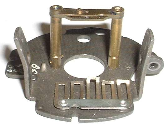
Twist the front trim ring to remove the ring, glass, seals and light guard. Remove two screws in back to free the works from the case. Tilt forward to bring the faceplate slightly ahead of the case on the right side. Peek in behind the faceplate on the right side to find the reset gear and shaft assembly shown in these pictures.
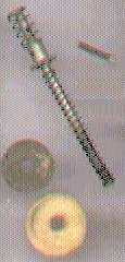

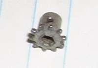 Note the position of all parts for reassembly later. At the bottom inside there should be a felt dust seal, a thin metal pressure washer, and a long spring to hold the dust seal in place. Above this find the reset gear with another stronger spring on top. The gear sits on top of an alignment plate and is held on the shaft with a small split pin.
Rotate the shaft as necessary for access to the pin. Use a small flat blade screwdriver or small long nose pliers to un-bend the legs of the split pin and reform it to straight condition. Rotate shaft again for access to the head of the pin. Use a crochet hook or small long nose pliers to pull the pin and free the gear from the shaft. Pull the shaft out the bottom and catch the small bits that fall out as you remove the works from the case.
Reassembly is the reverse of disassembly, but of course you get to fiddle more with the small tools to get all the little bits back in place.
Addendum December 2008:
I was told the little gear in the picture above is upside down, which it is, but that's not the problem. Apparently there are some variations on this design. The input shaft shown is straight and plain on top so the shaft can be pulled out of the gear. Some others may have a flange cold headed at top end of the shaft so the shaft will not pull out the bottom even after removing the split pin. One person has reported removing the split pin, then moving the obstructing reset arm a bit to one side, and then pushing the shaft upward enough to allow removal from the case. I have another report of a Smiths speedometer (possibly a little newer issue) having a molded nylon reset gear. This was secured to the shaft by a press fit straight steel pin, flush at both ends.
Addendum January 2010:
Not sure I would recommend cutting the case, but here's a suggestion from Dave Headrick.
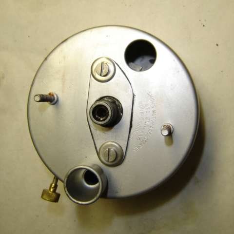
Slotted central hole elongated to allow easy removal of mechanism. Doesn't help getting it out the first time but does help reassembly and future interventions. To keep dust out of the case I fabricated a plate to cover the hole and used a rubber gasket.
Addendum, Sept 2010:
Click for details of a
needle puller tool.
|
Addendum, March 2010:
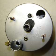
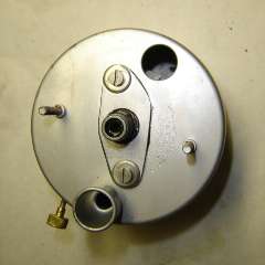
For those people who are not afraid to pull the needle off the shaft, removing the works from the case is easier. Simple put, pull the needle off the shaft and remove two screws to remove the face plate. Then remove two screws in back, and the works comes out without removing the reset shaft (but maybe remove the knob from the shaft). The trick here is to pull straight forward on the metal hub without pulling the plastic needle off of the hub and without bending the shaft.
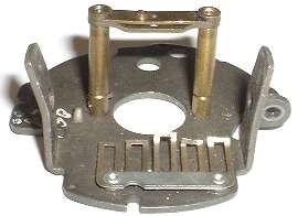
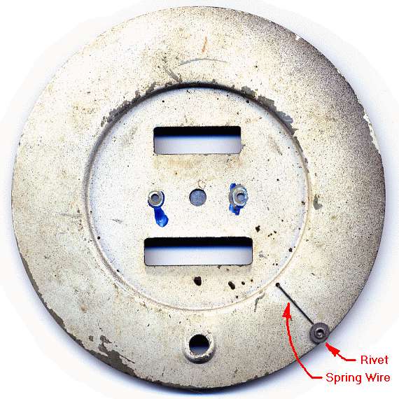
There is a metal bar behind the faceplate running between the two screw locations, otherwise no other physical support behind the faceplate. If you would devise a lever or a puller, the only good place to apply pressure to the face plate is on the screws. The metal bar is composed of a thin brass bar in front of a thicker steel bar, and one small screw just off center. The screw is used to pull the two bars together, bending the thinner brass bar slightly in the process. This is the adjustment to minimize end float in the output shaft. Do not pry against the faceplate in between the screws, as this might damage the bearing support for the output shaft.
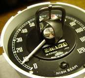
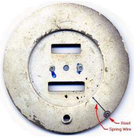
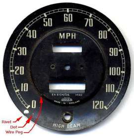
When it is time to reassemble, install the works in the case first with screws in back of the housing. Then install the face pate with two screws. To get the needle in correct orientation, hold the instrument upright, and position the needle to point at the small white dot just below the "0" point on the face plate, and press the needle firmly onto the shaft. Then depress the spring wire zero peg, swing the needle upward past the peg, and release the peg wire to spring back forward. The needle will then come to rest gently against the peg.
|