The MGA With An Attitude
Wiring Harness Installation, Wire By Wire, Page 1 of 5 - ET-100I
ET-100I - Grounding, Tools, and Resistances - (you are here)
ET-100J - Primary Lighting Circuits
ET-100K - 1500 Type turn signals and brake lights
ET-100L - 1600 Type turn signals and brake lights
ET-100M - Everything that is not lighting circuits
Grounding, Tools, and Resistances
At 05:24 PM 11/7/2007 -0700, Matt Szechenyi wrote:
"In 'sequence of wiring' you suggest 'individual circuit testing of almost every wire being connected'. Could you be a bit more specific here? Perhaps a step by step for one sample circuit would help me understand the approach. Are we looking for continuity in the circuit, or trying to rule out ground fault, etc??, and what device should I use: simple test light, multimeter?
Okay, hang onto your seat and grab another beverage. I am about to write the excruciating details for another long (and possibly boring) web page (or several web pages) recommending a sequence of hookup for every wire in the car. By the time you get half through the first page of hot wire connections you should get the hang of what's going on to test each wire and prevent burning anything.
A new wiring harness should never have an internal wiring error (although there have been a few really strange exceptions). Every wire in the harness is a single wire with two exposed ends, no hidden terminations or splitters inside the harness wrap, and no two wires are connected together inside the wrap. If you wanted to take the time to fiddle with it you could use an ohm meter or continuity tester (test light with battery) to "buzz out" each wire, finding the opposite ends of each wire to be electrically common and not connected to any other wire in the harness. Knowing this, you can deal with just one wire at a time for installation.
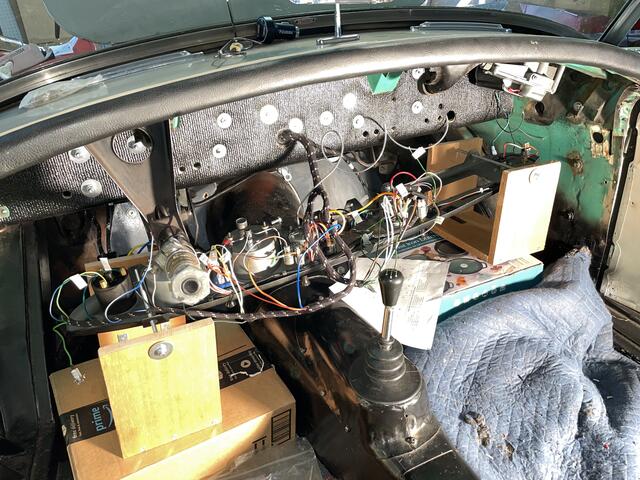
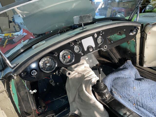
The instrument panel (dash) can be assembled on the work bench with all instrumens and switches. The dash harness can also be installed on the bench with the harness running aross top of dash just below the top flange. For connecting the main harness wires to the dash, you could sit on the tunnel with dash face down on your knees to do the wiring, then offer the dash up to the body cowling for attachment after wiring. Assuming this will not be all at one sitting, the face-down dash can be placed on supports above the floor for convenience.

You can connect all the ground wires first, plugging together all the black wires and attaching chassis grounding ends. Be sure to scrape a bare spot through the paint at chassis ground connections, or use a star washer that will bite through the paint to base metal for a good ground connection. The only load devices having housing grounded to chassis are the starter motor (ground return through engine grounding strap), and fuel sender unit (grounded through steel line from tank to fuel pump). Instrument illumination lamps need a ground connection on the instrument housing, which should in turn have a black grounding wire from the harness.
The map lamp grounds on the dash panel (which will hopefully be grounded on the body). Same for the turn signal warning lamp. Scrape a little paint off the dash panel to get ground for these two lamps (or add a ground wire if you don't want to remove the paint). Do not count on the dash panel being grounded to the car body or chassis. A restored car with good paint will often result in a non-grounded dash panel. Machine screws usually do make electrical connection through the threads, but commonly do not connect through paint under the screw head. An alternate path to ground for the dash panel is where instrument mounting brackets touch back of the panel, but those points may also not connect ground unless the paint is scratrched from the panel.
Grounding points on the chassis for black wires in the harness are as follows.
Battery grounding cable is (originally with twin 6-volt batteries) attached to frame just outboard from the LH battery carrier, above the center exhaust hanger point. Scrape paint off of frame for good electrical contact to cable end.
Engine is grounded to frame with a heavy cable across the LH engine mount. Scrape paint off of area under cable ends for good electrical contact.
Main harness is grounded with a ring a lug on the body on the front side of the upper firewall near the fuse box. Use an internal tooth star washer to bite through paint for good electrical connection.
Two black ground wires are connected to the "E" terminal of the control box. One of these is ground for the wiper motor, while the other is a chassis ground wire.
Main harness has another ring lug for grounding at the RF corner of the body. This (originally) attaches with a hex nut to an extra length fender bolt, second bolt up from the air pan in front of the radiator.
Side harness has a ring lug to ground on a frame tab bracket underneath and frame arch above the rear axle on the RH side. Scrape paint off of the bracket for good electrical connection to the ring lug.
Fuel pump (original SU type) has a black wire with a ring lug to ground with a hex nut on an extra length bolt for the rear vertical plywood floor board. I believe it should be the second bolt half way down, as the top bolt is too difficult to reach under the fixed battery cover area.
Fuel tank (sender unit) originally grounds through the steel fuel pipe between tank and fuel pump. If this pipe is cut and reconnected with rubber hose, then install an additional black ground wire between one of the fuel level sender mount screws and the tab on the frame nearby.
Turn Signal Relay (for 1500 model only) must be grounded on the bulkhead for the relays to work. Consider using star washers on the back side of the bulkhead to have ground connection through the paint and mounting screw.
Turn Signal indicator lamp must be grounded on back side of the steel dash panel. Scrape paint off back of panel at this point for good electrical contact. For an accessory wood dash, add a black ground wire.
Map light fixture must be grounded on the steel dash panel. Scrape paint off perimeter of hole in steel panel for good electrical contact. For an accessory wood dash, add a thin metal plate and black ground wire.
This dissertation will assume that all of the electrical devices and harness are already mounted, and you will now be connecting all of the wire ends. Start with connecting the battery (batteries) and connect the heavy cables to chassis grounding point (sans paint) and to the starter switch. That brings power only to the starter switch. You may (optionally) install a battery cut-off switch at this time, a very handy device if it is located where easily accessible. You might also do the starter motor hookup at any time, as this is just a single heavy cable from starter switch to starter motor. Also be sure there is a heavy cable between engine and frame (usually across the LH engine mount). The pull switch can then crank the engine with no other wiring connected.
You may use a 10 or 15 amp battery charger in place of a real battery. This will supply enough current to power up lighting systems, or everything else in the car without the lights, but will limit total current low enough to avoid burning wires or even blowing fuses if you should encounter a short to ground. The battery charger will not supply enough current to test a starter motor.
Keep a test light close at hand at all times (to check for power) whenever dealing with any electrical wiring. This is a simple tool that will serve easiest for 90% of all vehicle electrical testing and de-bugging.
An ohm meter can be used to check resistance for an end load device before connection (more on this below).
A continuity tester (test light with internal battery) can be used to find common wire ends and check contact across connectors, such as checking to be sure two or more bullet wire ends are actually connected when plugged into a female snap connector.
A test light and jumper wire can be used in place of the continuity tester to connect power and ground and look for light (good connection).
A DVM (digital volt meter) or DMM (digital multimeter) can be used in a pinch (if you follow the instructions) in place of a test light or continuity tester. For minimal content in a traveling tool kit you might pack a pocket size DMM and leave the test light and continuity tester home. The DMM is also good for adjusting a voltage regulator, testing a battery, or searching for a high resistance connection.
Switches have infinite resistance when switched off, and near zero resistance when switched on. Any switch contact showing more than 1/4 ohm resistance (250 milli-ohm) needs to be cleaned or replaced immediately. The sole exception is the panel lamp dimmer switch (a wire-wound potentiometer) that goes from near zero to high resistance as it rotates. Switches are easily tested before connecting using a continuity tester (test light with battery) or a test light and jumper wire to connect power and ground (and get light or no light). Switches need to be open circuit when off, closed circuit when on, and never shorted internally to chassis ground on the housing.
End load devices (if they are not defective) always have some internal resistance that will limit current draw. Higher resistance allows less current and lower power draw. If you are the cautious type you may check resistance of each load device before connecting a hot wire. In particular, be sure the device input wire or terminal is NOT shorted to ground with zero resistance. Also use rubber grommets for body pass-through points and p-clips or band-wraps to support the harness where appropriate, so you will never have the harness wrap or insulation abraded to cause a wire short to ground. During installation, do not let bare wires touch any grounding point.
Load Device Resistance:
Dash light and license light bulbs are 4 watts with resistance about 36 ohms
Parking light bulbs are 6 watts with resistance of about 24 ohms.
Brake light and turn signal bulbs are (usually) 21 watts with resistance of 6.5 ohms.
Headlights in the 40-60 watt range have resistance around 2.4 to 3.6 ohms.
Light bulbs will never have an internal short to ground, but a lighting fixture might.
Starter motor will be extremely low resistance, maybe 0.05 ohm, to draw hundreds of amps. Because working resistance is so low, it is at first tough to tell if a starter motor has a short to ground. That is covered in a separate tech article.
Horns will be low resistance, maybe about 1 ohm to consume high power.
Fuel pump will be medium resistance with moderately high current, but is very intermittent (tick, tick).
Ignition coil (standard) is about 3.2 ohms through the primary winding (side terminals).
Ignition coil (high output) may be about 2.6 ohms through the primary winding.
Ignition coil with 1.6 ohms through the primary winding is the wrong part for MGA. (The 1.6 ohm coil would be a 7 volt coil for use in a 6-volt system or in a 12 volt system with a series wired ballast resistor).
Heater motor may be about 3 ohms
Wiper motor may be about 3 ohms.
Fuel gauge (original MGA type) is about 60 ohms between B&T, 100 ohms between T&E (case), and 160 ohms between B&E. You need to disconnect the sender wire from the gauge when checking resistance to Earth.
Fuel sender unit is 0-70 ohms depending on fuel level. This is the only end device that goes to zero ohms (when empty) and must be connected in series with the fuel gauge.
Turn signal relay for 1500 cars is normally closed between terminals 3,5,7, normally open at terminals 1,2,6, and shows high resistance to ground on case for terminals 4,8 (the relay operating coils).
Turn signal flasher unit when at rest with no load has some resistance between B&L and open circuit between B&P.
Brake switch is normally open with no pressure and closes with application of brakes.
|