The MGA With An Attitude
Wiring Harness Installation, Wire By Wire, Page 2 of 5 - ET-100J
ET-100I - Grounding, Tools, and Resistances
ET-100J - Primary Lighting Circuits - (you are here)
ET-100K - 1500 Type turn signals and brake lights
ET-100L - 1600 Type turn signals and brake lights
ET-100M - Everything that is not lighting circuits
Primary Lighting Circuits
When you begin connecting power wires, follow the power feed circuit path starting at the source, and connect one wire at a time, checking and testing each wire and each device as you go.
Start connecting power wires with the heavy brown wire from starter switch (battery cable side) to control box terminal "A". A test light at starter switch (battery cable side only) should show hot. Connect the brown wire there. Then test light at other end of the wire should show hot. Connect that end to control box terminal "A". The screw post terminals for A and A1 should then be hot. Leave the other brown wire disconnected from the control box at this time, as that is the feed wire for the horn circuit. Two black ground wires can be connected on the "E" terminal, but leave D and F wires disconnected at this time. Connect the brown/blue wire from control box A1 to the ignition switch. The ignition switch should then be hot on the input terminal and cold on the output terminal. Switch on should make output terminal hot. From here on, leave the ignition switch off unless you are testing a downstream circuit after connection.
Your one caution/fear through all this is to NOT accidentally connect a power wire directly to a ground connection (or to any device shorted to ground). Connect only one power wire at a time and verify the circuit before going on to the next power wire. Be ready at all times to switch off or disconnect immediately if you cause a heavy electrical arc or start to heat a wire. To be safe connect a brake light bulb (or two in parallel), or 3-ohm minimum 50-watt power resistor, in series with your power wire to limit current. If you short this to ground the resistor will heat up like a 50-watt light bulb drawing 4-amps, but it will not burn a wire.
Lighting circuits are next. Connect brown/blue from ignition switch input side to Lighting Switch input. Lighting switch should then be hot on input A and cold on outputs S1,S2. Pull switch half way to get hot on S1. Turn and pull switch full out to get hot also on S2. Leave switch off when connecting more wires, and turn on to test each device after connection.
Connect blue from Lighting Switch S2 to Dipper Switch input. With LS full on (pull-twist-pull) power should alternate between DS output terminals each time DS is pressed. DS output terminals are interchangeable, while input terminal is always connected to one of the others. Be sure you get the right terminal for input. Then connect remaining wires to DS, blue/red on one and two blue/white on the other. Plug the high beam indicator lamp (with blue/white wire) into the speedometer to make ground connection. Turn LS on and kick DS to verify indicator light works on and off.
Under front wings, connect headlight wires. At Right Front you can use test light to verify power on blue/white and blue/red wires from main harness with LS on and kicking DS. At RF plug together three blue/white into a 4-way snap connector, plug three blue/red into another 4-way snap connector, and be sure black wires (4 including parking lamp) are plugged together in another 4-way snap connector. Turn LS on and kick DS to verify that high and low beam lights work, and high beam works in tandem with the dash indicator lamp (then switch off). At Left Front plug two blue/white together with a snap connector, plug two blue/red together with another snap connector, and be sure black wires (3 including parking lamp) are plugged together in a 4-way snap connector. Turn LS on and kick DS to verify all high and low beam lights work, and both high beams work in tandem with the dash indicator lamp.
Be sure all of this works before going on. If anything does not work, get back to basics with test light to check/verify power input and good ground connections. Work back toward the power source until you find things work properly, then work forward toward end load devices to find where things don't work. When you suspect a faulty load device, you can disconnect it from the harness, and use jumper wires to connect power and ground to the load device for testing and/or repair. Use the load resistor in the power wire to be safe.
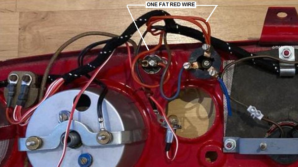
Parking light circuits (red wires) are next, starting behind the dash. Find five red wires on harness near lighting switch. There is a trick here.
 Use a continuity tester to poke around among these five wire ends until you find two that are electrically connected (these are the same wire). One of these ends must be connected to the fog light switch. Also connect the only red/yellow wire to the other side of the fog light switch. Connect the other four reds to S1 terminal on the Lighting Switch. The opposite ends of the remaining three red wires need to be connected to the panel light switch (rheostat), map light switch, and a 4-way snap connector in the engine bay near the starter switch.
Connect four red/white wires to the second terminal of the Panel Light switch. Plug all four of the instrument lamps (bulbs with red/white wires) into the instruments for grounding. Turn LS on and rotate PL switch to verify instrument lamps work. If not, check for power at PL switch output, good ground for each lamp, good connection for bulb in socket, and good bulbs. When all panel lights work, turn PL switch to off position and leave it there until completion of other red wire circuits. Connect Map Lamp wire to Map Light Switch. Turn LS on and turn MLS on, and verify ML works. If not check for power at MLS output and good ground between ML and dash panel. When it works, turn MLS off until completion of other red wire circuits (and turn off LS).
At this point, if you have a single fog lamp (or a single driving lamp) mounted, you can go to the front and connect the red/yellow wire to the fog lamp using a female snap connector. If no fog or driving lamp is to be connected, then install a female snap connector on the red/yellow wire to prevent accidental grounding of a hot wire (and skip the rest of this paragraph). Most auxiliary lamps will have a ground wire in addition to the power input wire. The ground wire needs to be connected to chassis ground. This is (originally prescribed) to have a black wire plugged into one of the 4-way snap connectors with other black wires up front. Alternately a fog lamp might be grounded on the bumper or at a separate body or chassis bolt. Switch on LS to first position, also switch on FS (fog light switch), verify operation of the fog light, then turn off FS and LS. If you have more than one auxiliary fog or driving lamp you may need to change one of the 4-way snap connectors to a 6-way connector to accommodate all the black ground wires. Then again, more than one auxiliary lamp will also require installation of a relay and separate power feed wire (which is covered in other tech articles).
In engine bay near starter switch, verify power on red wire snap connector when LS is on (first position only), then turn LS off. Plug in red wire for front harness only, then verify power on red wire at RF corner with LS on, then switch off. At RF corner plug together three red wires into a 4-way snap connector, verify all black wires are connected, turn LS, verify operation of RF parking lamp, then switch off. At LF corner plug together two red wires into snap connector, verify all black wires are connected, turn LS on, verify operation of LF parking lamp, then switch off. Mind you we are not working with turn signals yet, so those wires should still be disconnected.
Back in the engine bay near the starter switch, connect the one remaining red wire (for the side harness) into the 4-way snap connector with the other reds. Turn LS on, use test light to verify power on red wire at RR corner, then switch off. Plug that red supply wire into a 4-way snap connector along with the red wire going to the RR tail light (and verify black wires are connected). Connect red wire inside RR lamp fixture (and verify black ground wire is connected). Turn LS on (half way), verify operation of RR tail light, and switch off. If anything is amiss, fix it before going on. The tail light should be on low light. If it appears to be on bright light the bulb may be installed wrong (not likely because it is keyed) or wires inside the lamp fixture may be connected wrong. The bulb shell must connect to black wire for ground. The red wire must connect to the low filament in the bulb. Make this work before going on.
Go to RR corner and plug in the red wires that will go to LR lamp and number plate lamp. If you can know which is which then do one at a time. Do not let the output ends get shorted to ground while in process. Go to LR corner, switch on, verify power on red wire, then switch off. Connect red wire inside LR lamp fixture, verify black is also connected, switch on, verify low light lamp works, and switch off. If it doesn't work right, fix it immediately.
Then go to the RR corner to plug in the remaining red wire (if not already done). Go to number plate lamp, switch on, verify power on red wire, and switch off. Connect red wire inside number plate lamp, and verify black wire is connected. Do not get these mixed up. If you get any red wire connected to ground it can burn a wire (or wires). A short to ground would heat up the red wire in the side harness that is carrying power for three lamps at back. It would cause even more heat in the red wire between LS and snap connector in engine bay, as that one is carrying power for five or six bulbs (28-32 watts) in addition to the short to ground. The lighting switch may also get hot (and possibly be damaged).
When you have headlights, dash lights, parking lights, and number plate light(s) working, take a break, as you have more than half of the harness finished, none of which is originally fused. More in the next message.
|