The MGA With An Attitude
CONTROL BOX BENCH TESTING - ET-121
This article is submitted by: Patrick B. Harris, Jr.
I posted a question on the mgs list at autox asking if there were any ways to check a control box. Ive taken some resistance readings from three RB-106-2 control boxes just to see if there are any significant differences/patterns/etc.
First, the one that had failed, causing me to ask the question initially. Readings from it appear to not fit the pattern shown by the other two.
Second is one which I received about a week ago from Moss and it needed to have the contacts cleaned before it could be adjusted. Perhaps if I had cleaned it first I may not have needed to do any adjusting.
Last is one that came from a parts car that had been sitting for about 10 to 15 years. It appears to have characteristics in common with the new control box but would the storage conditions and age possibly lead to the resistance values being a tad higher than when new?
| TESTING CONTROL BOX VALUES BETWEEN TERMINALS IN OHMS
ORIGINAL CONTROL BOX - failed in use |
| |
E |
D |
F |
A1 |
A |
| Cutout Contacts |
Open |
Closed |
Open |
Closed |
Open |
Closed |
Open |
Closed |
Open |
Closed |
| E |
|
|
8.0 |
8.0 |
15 |
15 |
∞ |
8.0 |
∞ |
8.0 |
| D |
|
|
|
|
6.0 |
6.0 |
∞ |
0 |
∞ |
0 |
| F |
|
|
|
|
|
|
∞ |
6.0 |
∞ |
6.0 |
| A1 |
|
|
|
|
|
|
|
|
0 |
0 |
| A |
|
|
|
|
|
|
|
|
|
|
| TESTING CONTROL BOX VALUES BETWEEN TERMINALS IN OHMS
NEW CONTROL BOX - just purchased/installed - (This is the good one) |
| |
E |
D |
F |
A1 |
A |
| Cutout Contacts |
Open |
Closed |
Open |
Closed |
Open |
Closed |
Open |
Closed |
Open |
Closed |
| E |
|
|
4.5 |
∞ |
4.5 |
∞ |
∞ |
4.5 |
∞ |
4.5 |
| D |
|
|
|
|
0 |
0 |
∞ |
0 |
∞ |
0 |
| F |
|
|
|
|
|
|
∞ |
0 |
∞ |
0 |
| A1 |
|
|
|
|
|
|
|
|
0 |
0 |
| A |
|
|
|
|
|
|
|
|
|
|
| TESTING CONTROL BOX VALUES BETWEEN TERMINALS IN OHMS
FROM PARTS CAR - rusty, dusty, crusty :-) |
| |
E |
D |
F |
A1 |
A |
| Cutout Contacts |
Open |
Closed |
Open |
Closed |
Open |
Closed |
Open |
Closed |
Open |
Closed |
| E |
|
|
5.5 |
5.5 |
6.1 |
6.1 |
∞ |
5.5 |
∞ |
5.5 |
| D |
|
|
|
|
0.9 |
0.9 |
∞ |
0 |
∞ |
0 |
| F |
|
|
|
|
|
|
∞ |
0.9 |
∞ |
0.9 |
| A1 |
|
|
|
|
|
|
|
|
0 |
0 |
| A |
|
|
|
|
|
|
|
|
|
|
Testing and adjusting the Control Box
Objective: To "bench test" and adjust the settings of the control box.
Big assumptions: The control box is functional and only needs adjusting and the contacts on the cut out bobbin are CLEAN.
There is one setting which is not mentioned in the workshop manual but it needs to be checked first.
When viewed from the front of the control box - that would put the terminals and letters facing you - the bobbin on the left is the voltage regulator switch and the bobbin on the right is the cut out voltage switch. At the top of the voltage regulator is a screw and locking nut - think "adjusting the valves". The large plate which is directly above the bobbin is attracted downward by a magnetic filed when current travels in the bobbin. The space between the bottom of this plate and the top of the bobbin is referred to as the "air gap" and it must be between 0.012inches and 0.020 inches. The space can be adjusted by backing off on the locking nut and turning the screw either in or out. See page 7 of the Lucas Generator and Control Box Tests available at Barney's Book Shoppe for complete details.
Part of the reason for having the control box is that an unregulated dynamo can put out enough voltage to "fry" your generator. The opposite side of the coin is that a poorly adjusted control box may not allow the battery to maintain a charge.
The control box has 2 adjustments for controlling the output level of the dynamo and the procedure can be found in the shop manual. The following connections follow the shop manual if you consider the power supply to be the dynamo. The shop manual has the A1 and A wires disconnected. - same here.
I used a variable power supply that can provide a maximum of 18v dc as a substitute for the dynamo output. High enough to exceed the maximum permissible voltage level of approximately 16v for which you will be adjusting. The output of the dynamo increases as its rpm increases and vice-versa. You mimic this by rotating the power level knob on the power supply.
When installed on the firewall the E terminal is for the ground (Earth) connections. (If yours is a negative ground you'll need to swap the leads so that the testing of a control box mounted on the firewall will be the same but, on the bench it makes no difference.
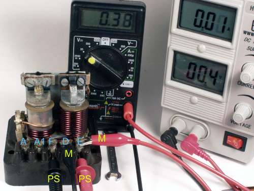
Bench Test Setup with a power supply and volt meter
The positive lead of the power supply (PS) is connected to the E terminal of the control box.
The negative lead of the power supply (PS) is connected to the F terminal.
The negative lead of a voltmeter (M) is connected to the D terminal.
The positive lead of the voltmeter (M) is connected to the ground, or E terminal
In the first picture the power supply has been switched on at a low voltage level and the voltmeter connected shows almost the same reading. Both should have the same reading until the voltage from the power supply exceeds the regulated voltage. This value is supposed to be set in between 15.8 volts to 16.7 volts. The workshop manual gives the specific voltages based on ambient temperature. I have adjusted mine between 16.1 volts and 16.7 volts.
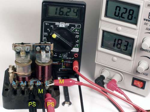
Adjusting Control Box
In the picture below the voltage from the power supply exceeds the desired voltage but the control box is "controlling" the voltage at the appropriate level.
Side note from Barney: This procedure does work for bench testing and adjustment, but this is not exactly the way it works in the car. When the control box is properly connected to the generator, the regulator relay will be controlling the input voltage to the Field coils. This square wave output (average) voltage could be anything between full system voltage at low engine speed to some voltage considerably lower at higher engine speed. As engine speed and dynamo output increases the field voltage (or square wave duty cycle) is reduced to prevent overcharging. This in turn controls the dynamo output voltage.
Bench Testing and Adjusting using a power supply and volt meter
Before making any reading I'd suggest you play with the system to see how it works. Don't worry about making any adjustments or voltmeter reading at this point. If you have a control box which is not working STOP - DO NOT PASS GO. PROCEED IMMEDIATELY TO THE BOTTOM OF THE PAGE.
I'd start the test by running the voltage up to see if the bobbin on the right is working. The movement on that bobbin is far easier to see than that of the left side bobbin. If you want to, disconnect the power supply lead to the F terminal and set the power supply to 18 volts. Tap the power supply lead on the F (or D) terminal - if the bobbin is working you will have an audible tap/click noise - like a telegraph key. While doing this you may want to have the power set at a level high enough to have these contacts remain closed and check the magnetic field on the top of each bobbin - a small screwdriver place on top of the bobbin will be attracted to the bobbin - stronger attraction on the right bobbin than on the left bobbin. Another thing you should do is to examine the movement of the contacts on the right side bobbin. Slowly increase the voltage and the contacts will start to close. After they have completely closed start decreasing the voltage. The points will open. There should be a difference between the opening voltage and the closing voltage. These are the cut out voltages you will need to adjust. The workshop manual states that correct values should be between 8.5 volts and 11.0 volts BUT the workshop manual gives instruction for setting the open-circuit voltage first so I do the cut-out voltage adjustment last.
Make sure the connections are as pictured and turn the power supply level to 0 volts before switching the power supply on. Slowly raise the voltage and watch both voltage readings. If the control box reading is higher than the 16.1 volt - 16.7 volt range then the control bobbin must be adjusted. To prevent heat build up in the system switch off the power supply. Make your adjustment on the back side of the control bobbin - screw in to raise voltage/screw out to decrease voltage. Repeat until you get it adjusted correctly. Heat will build up quickly so don't forget to do the OFF/ON bit.
Side note from Barney: This regulator relay adjustment is very sensitive. A small turn of the adjusting screw makes a large change in controlled voltage output. Perhaps 15 degrees rotation of the screw may make as much as one volt change of output. The relay frame is also sensitive to touch, so you must not be touching the relay with tools or fingers when you check the output voltage.
You should already know what the contact movement on the right side bobbin looks like. Once again don't forget the heat build up problem. Working up from 0 volts is ok but you should also know the approximate voltage at which you can start. As the contacts close completely that will be one of your subsequent readings. As you slowly decrease the voltage level you will notice that the contacts do not immediately separate. Some residual magnetism in the bobbin holds the contacts together until the voltage drops sufficiently. This will also be one of the reading you will need to set. If the closing and opening values are not correct the adjustment screw is just behind the cut-out.
BOTTOM OF THE PAGE :-)
I would suggest that you first take a small piece of very fine sandpaper (800??) and slide it between the contacts on the right side bobbin in order to clean them. Put the paper between the contacts and pinch the contacts together gently so that the sliding sandpaper meets a little resistance. I installed a new control box only to find that it was "out of adjustment". .According to the supplier some oil or other preservative was coating the points and they suggested cleaning them as mentioned. It worked too! :-)
|