The MGA With An Attitude
IGNITION SWITCH Terminals and Wiring, MGA - ET-124
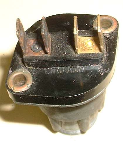
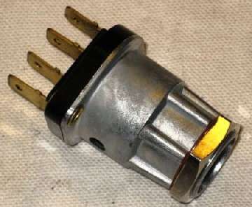
My first comment on the MGA ignition switch has to be a concern for the type of terminals on the back. Original issue switches used two screw post terminals as shown below left (photo from a lighting switch). These are extremely reliable, and I have never known one to fail in use. At least since the mid 80's it is common for replacement parts to have Lucar push on connectors as shown below right. This design is an impending failure, and if you drive the car long enough, it will happen.
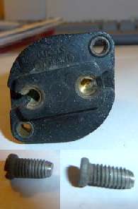
AHH5369 Ignition switch, 1500, 1600, Twin Cam - (with set screw terminals)
3H2825 New part number; - AHH5369 not available, use 3H2825
The new part number has the spade terminals, introduced in late 1600 production.
The reason for this comment can be obvious when you look at the wiring connection diagram. All electrical current used by the car, other than starter motor and horn, arrives at the first terminal on the ignition switch on a fat browN/blUe wire. From there another NU wire continues on to the lighting switch. With the screw post terminal these two wires are intimately screwed together, so the lighting current passes directly from one wire to the other. Total current coming in may be up to 20 or 22 amps with all accessories switched on. About 12 amps of that goes to the lighting switch (high beams, parking lights, dash lights), and about 10 amps may go through the ignition switch (ignition coil, fuel pump, heater blower, wiper motor, fuel gauge, brake lights, turn signals).
When using the Lucar type terminals, all of the incoming 22 amps will be running through one push-on terminal. About 12 amps of that (for lighting) will be going out on another push-on terminal on the same connector block. On the output side of the switch, about 10 amps will be split between two push-on terminals (one being only for the ignition warning lamp). Aside from all the inherent problems with push-on connectors, the input connector here would be carrying 22 amps through a single wire terminal, about the same as output current of the generator. Difference is, the late issue generator has a much larger push-on connector for dynamo output designed to handle the higher current. The smaller Lucar connector on the ignition switch is not up the task for such high current. If/when there is the slightest looseness in this connector, the high resistance joint combined with high current will generate heat, and quite a lot of it. With time the heating causes the Lucar female connector to lose its spring temper, and then it gets progressively looser and hotter until it ultimately burns insulation off the wire near the connector, and the connection fails.
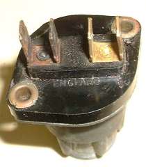 Another issue with this aftermarket switch is the rivets securing the male Lucar connectors to the switch body. They are none too sturdy, and they carry all of the electrical current going through the switch. If the rivet gets loose (a common malady) then the loose contact makes high resistance that will cause more heating (along with lower circuit voltage). Over the years this switch has suffered from both loose push-on connectors and loose rivets, and has cooked the connectors more than once. The switch still works internally, but you can see the discoloration and corrosion on the power input terminal.
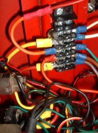 My solution to this problem aside from repairing or replacing the switch) was to install a cheap screw terminal barrier strip (from RadioShack). I attached this part to the body brace channel, and started by running the incoming fat browN/blUe wire to the barrier strip. From there run separate wires to the ignition switch and lighting switch. As a convenience I also run one wire from the ignition switch output back to the barrier strip where it is then split to separate wires. The input wire on the ignition switch now only carries the current that actually goes through the switch. All other wires originally related to the ignition switch terminals are now on the (more reliable) screw terminals of the barrier strip. This also provides for additional termination points for accessories such as radio, cruise control, intermittent wipers, cell phone charger.
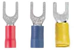
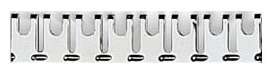
The jumper strip shown above can be broken to shorter length to connect together two or more terminals on the barrier strip. Use narrow fork terminals shown at right to connect wires to the barrier strip.
|