The MGA With An Attitude
TURN SIGNAL CONTROLLER, Electronic Delay and 4-Way #2 - ET-249A
This device is supplied by Signal Dynamics. I believe it will work for the MGA 1600, but will not work for the MGA 1500 where brake lamps are used for rear turn signals.

This cannot be used with the original time delay switch, unless the time delay function of the switch is somehow defeated. Switch (or switches) must be momentary contact type. Apparently you have to hold the switch for some period of time to switch on the turn signals, one second for lane change, two seconds for normal turn signals, or four seconds for long delay if you get caught by a red light. I think that would bother me, having to hold the switch for two seconds just when I need to downshift and change lanes. Any poke less than one second is apparently a cancel signal.
See wiring diagrams below. Someone's feedback note mentioned wiring diagram on the back of the module. There is no indication on the web site that these modules will not work with the earlier style turn signals where brake lamps are used for turn signals. Also it does not include the original safety feature where it stops blinking if a bulb is burned out or disconnected (as it is not load sensitive).
 Can work for MGA 1600. Will not work for MGA 1500. Can work for MGA 1600. Will not work for MGA 1500.
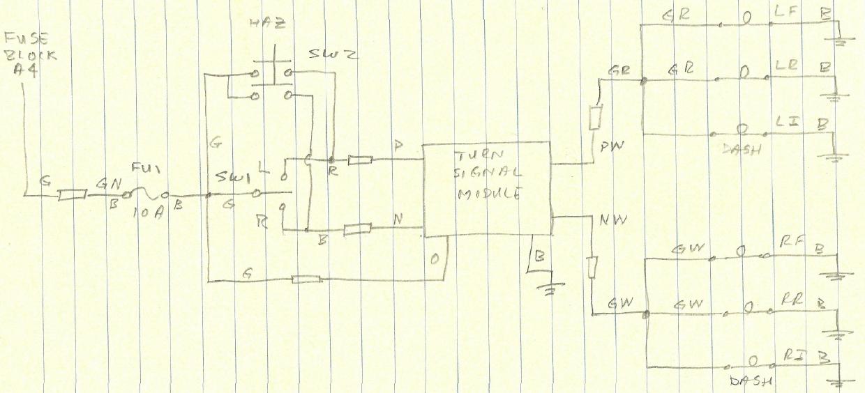
The following diagram has color codes to match the MGA 1600 wiring harness.
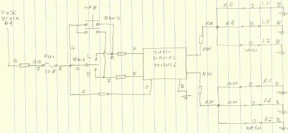
If you install two diodes from PW and NW, the dual output can be used to trigger a single signal lamp on the dash as original for MGA.
Per the 1600 wiring diagram, the overall 12v+ supply wire from the fuse block terminal A4 to the flasher (43) is green, G, then from the flasher, green/brown, GN goes to the switch (46) common. The light green, LG, wire goes to the panel indicator lamp (49).
With the module, the flasher is not necessary. To bring 12v+ power in to the new dash switches, connect G to GN (bypassing the flasher), then connect GN to the new 10A circuit fuse. From the new 10A fuse, 12V+ then goes to the new turn signal switch (TSS - Littlefuse 75701) common and to the orange 12V+ Module wire. The left TSS connects to the purple, P, module wire, and the right to the black TSS wire. From the module, purple/white, PW, connects to the green/red, GR, wire, which is the left turn signal lamp circuit, and black/white, BW, connects to green/white, GW, which is the right turn signal lamp circuit.
The modules hazard function requires that both left and right momentary switches be pressed simultaneously, which is not possible with the rotary, momentary TSS. Accordingly, a DPDT
 push button is installed in parallel with the TSS so that pressing it engages the hazard function.(DPST will work, but I couldnt find one.) A second press cancels the hazard function.
If you do not have the original vacuum delay turn signal switch, or if your original switch does not work electrically, you can buy a similar switch without the delay function from Littlefuse
|