The MGA With An Attitude
HEATER MOTOR TECH - ET-212 - Pg 3 of 7
Here below is a picture of the major components of the motor along with all of the assembly fasteners. Just to the right of the mounting flange you can see the laminated steel core of the field coils, which is cylindrical with two flat sides. The long assembly bolts actually pass through the laminated core, while the flat side allows for passage of the power lead wires through the outer case. Just to the immediate right of the mounting flange you can see the triangular steel plate that is laminated into the field coil core. This triangular plate cannot be removed without destroying the field coil.
You may also notice that the mounting flange is still attached to that triangular plate. At this junction there are small rubber grommets that serve as vibration isolators, and the mechanical connection includes rivets and flat steel washers. The mounting flange cannot be removed without removing these rivets, which would surely destroy the rivets. Also the peened end of the rivet is facing the mounting flange, so it is not convenient to simply drill out the rivets. More likely you would use a small hand grinder to grind off the tip of the rivet for removal. Reassembly might then be done with screws and locking nuts, but you still need the flat washers, and also tubular metal spacers to provide the correct working fit for the rubber grommets. I have always found (so far) that these rubber grommets have been in good enough condition to be left in place, so the expedient thing to do always seems to be to clean and paint the mounting flange without removing it.
At the far right is the motor rear steel shell with a small rubber grommet where the power leads bass through the case. On the left is the front steel shell. This is the point in time when it is very convenient to clean and paint the entire motor housing, and to replace the rubber grommet for the power leads.
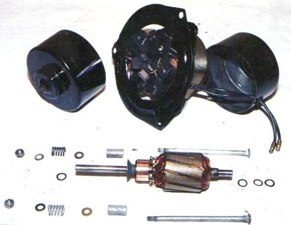
Lower in the picture you see the rotating motor armature. Each end of the armature shaft will have at least one thin steel thrust washer. At the right you can see more washers used to shim the armature to reduce end float. One of these pieces is likely to be a spring steel wave washer that is intended to apply a small endwise preload on the armature to eliminate any vibration which might be a possible cause of noise when the motor runs. Make note of the number and sequence of these parts to facilitate later reassembly in the same order.
Next to the armature you see the rest of the assembly hardware, shown in the order of assembly. The long thin bolts pass first through the rear steel cover, and then through the laminated core of the field magnet. Then there are tubular metal spacers that provide for location of the brush carrier plastic plate. This is followed by flat washers and compression coil springs, and then the front cover to be secured with lock washers and hex nuts. When the nuts are tightened the front and rear covers are squeezed tightly against the triangular center plate, rigidly supporting the field coil. The covers are a snug fit around the laminated field core, and there are bronze bushings in the covers to carry and locate the armature. When the front cover is installed it compresses the two coil springs to hold the brush carrier plate firmly in place.
|