
Report Spring 2000
1957 MGA Electric Vehicle Conversion
Millenergy
Team Members
Steve Gillespie
Richard Bergs
Chris Pickering
Jay Krueger
Hank Danford
MAE 4287
May 5, 2000
Abstract
The goal for this design project is to design a kit to convert a 1957 MGA convertible from gas power to electric power. The project includes researching all electrical components, removing the fossil fuel drivetrain, and installing the new electric drivetrain. Modifications to the brake and suspension systems are not included in the scope of the project. However, these modifications will be performed before the final product is delivered to the customer. The components included in the conversion are the motor, controller, batteries, battery boxes, wiring, and various brackets and hardware. The electric MGA will be designed to have a range of 20 miles of mixed driving. The total budget for the project is $115,068, which includes all components as well as design engineering for eight months.
The first four months of the project have been spent researching electrical drive components, testing the car's performance using the gas powerplant and modeling the required power output, removing all fossil fuel components, taking measurements of the car, and designing parts to adapt the new components to the car.
2
Table of Contents
| Introduction | pg 4 |
| Problem Statement | pg 5 |
| Analysis | pg 6-9 |
| Results | pg 10-22 |
| Conclusions | pg 23 |
| References | pg 24 |
| Bibliography | pg 25-26 |
| Appendix | pg 27 |
3
Introduction
In 1996 there were over 210 million cars registered in the United States. Only a small percentage of these cars were electric vehicles. The technology to make these vehicles more reliable and have a respectable range is still in its infancy. Many do not welcome the styling of electric vehicles; hence their popularity has yet to catch on with the general public.
Many factors are considered when choosing a new vehicle. Vehicle dimensions, power, acceleration, top speed, range, and styling are just a few of the main areas. Some of the criteria a prospective buyer considers affect the others. In electric vehicles, this becomes more important since the weight, aerodynamics, and system power greatly affect the performance and range. The vehicle weight is used to calculate the required power output of the motor, and the motor in turn determines the battery requirements. Low weight, rolling resistance, and air resistance become more crucial when dealing with electric vehicles than when dealing with gas powered cars.
Electric vehicles are more dependable because of the fundamental differences between them and fossil fuel. The electric powertrain has fewer moving parts and not as many mechanical dependencies. The dependency is more on the wires and connections between the solid state components.
Electric vehicles are the way of the future. This is not to say that an electric vehicle is limited to future designs. Many late model vehicles have been successfully converted and are used safely and efficiently every day.
4
Problem Statement
The basic problem for this project is to design an electrical drive system that is efficient, reliable, safe, easy to use, and high quality. The performance of the system should be equal to or greater than the performance of the car when it was gas powered. The biggest obstacle or limitation is the size of the car. The car is an 1860-lb convertible with little space that can be used for batteries and other components. Efficient, space-saving design is necessary in order to obtain the goals for the project.
The goals, or scope, of the project includes the following things:
Choosing a drive system and batteries for the conversion
Adapting an electric motor to the MGA's transmission
Choosing a mounting location and hardware for the electric motor
Choosing a mounting location and any hardware necessary to mount the motor controller
Choosing a mounting location and hardware for the batteries
Designing mounting brackets for the above components and boxes for the batteries
Chassis modifications to support the weight of the batteries, if necessary
Choosing route and mounting hardware for the wires and cables
Selecting a mounting location and hardware for miscellaneous drivetrain components such as: throttle control potentiometer, high voltage contacter, high voltage fuses and other safety devices
Upon completion of the project, team Millenergy will deliver the following:
One set of working drawings for all fabricated hardware
One prototype of all fabricated hardware mounted in the chassis
One set of documentation detailing the conversion procedure for Greenmountain's use
There are several areas of the conversion that are not included in the goals of this project. They will be completed before the final product is delivered to the customer. These include:
Modification to the suspension and brakes
Low voltage modification
Charging system
Passenger compartment heating
5
Analysis
As with any vehicle, one considers many options before deciding what motor to purchase. Engine size, range, styling, and comfort all play an important role in the choice. The same is true for an electric vehicle.
Before deciding which type and model of motor to use, a performance analysis was completed to determine an estimate of the power required to reach certain speeds. The vehicle is required to reach a speed of at least 45-50 miles per hour, be able to maintain this speed on flat surfaces and grades, and also have a range of at least 20 miles. Regenerative braking was considered as a means to increase the range of the vehicle. This allows the kinetic energy of the moving vehicle to be converted into electricity instead of wasting the energy as heat in the brakes. This energy can then be returned to the batteries, which will increase the range. In determining the range, the combined efficiency of the motor and controller, current draw, and revolutions per minute efficiency curve of the motor become a deciding issue.
The analysis was completed using a spreadsheet that was developed by Dr. Woods of the University of Texas at Arlington. The spreadsheet is a vehicle model that was developed for the school's SAE Formula Car team. Using a modification of the model along with coastdown data that was obtained by testing the project car, an analysis of the vehicle's performance and requirements could be completed. Figure 1 shows the required performance for the car with the performance of three different motors that are discussed in the results section.
Figure 1 - Required Performance
6
This model helped to narrow the motor choice since it showed the required power output and what speed the motor would turning at specific vehicle speeds. This helped to determine where the efficiency and peak power of the motor would be needed. After the power requirements were determined, the type of motor could be selected.
There are two types of electric motors being used in electric vehicles today: direct current (DC) and alternating current (AC). Each motor has advantages and disadvantages. With direct current motors, there are brushed and brushless to choose from.
Brushed DC motors are among the most commonly used. Their relatively low cost, availability, and lower voltage requirement make them very popular. In the motor comparisons, one of the most common, the FB1-4001, was used to represent the DC brushed systems. The motor is readily available and performs well. The downside to this system is the large current draw at low RPM, which is common with series DC motors. These types of motors start with high current draw and torque, but as RPM increases the current and torque decrease. Another drawback to this system is the regenerative braking ability. This system is capable of regenerative braking, but accessories would need to be added. This would increase the cost and complexity of the system. DC motors do not make good generators, hence the complication with the regenerative braking. If this system was to be implemented, the "regen" would more than likely be left off. [1] With this system, the car would have a top speed of 90 miles per hour. This would meet our speed requirement, but the high current draw would hamper the range of the MGA.
The type of system that was considered next was brushless DC. Many brushless systems are used on solar vehicles and electric bicycles. These motors are smaller than that of the brushed DC and AC systems. They require a slightly higher voltage, but draw less current than the brushed DC. In the motor comparisons, a package from Unique Mobility Inc. was used, specifically the CaliberEV 32 system. This system has a high torque output, high efficiency, and the ability to implement regenerative braking. Since the voltage is low, the power output of the system is also low. [2] This lower power output decreases the top speed to 80 miles per hour, which still meets our goal. The current draw is not too high, but the power output could be a problem. This system does very well up to 60 miles per hour. At that point, the vehicle requires more power than is available. This could cause a problem if the required power increased such as when driving on roads with appreciable grades. Another drawback to this system is cost and availability. This system was one of the most expensive considered and very few exist that produce enough power and/or torque for the MGA.
The third system considered was the AC system. The AC system was the second most expensive and the most complex of those considered. The prices for these systems are decreasing which is causing them to become more popular. This system is very compatible with regenerative braking and helps the range further by drawing low current. The General Motors EV1 uses an AC system very successfully. On the downside, these systems use a higher voltage. This voltage is more than twice the amount used on most brushed DC systems and almost twice the voltage of a brushless DC system. [3] This voltage is extremely dangerous and must be treated with respect. This is not to say that
7
the voltage in the other systems is not dangerous. All electric vehicles can be dangerous, but so can fossil fuel vehicles. This consideration aside, this system offers many benefits. As stated earlier, it offers "regen", uses lower current, and has a power and torque output that is very compatible with our vehicle.
The batteries perform two functions in an electric vehicle. The first is to store energy in the form of chemical energy and the second is to convert the stored chemical energy into electrical energy. The motor draws the electrical energy from the battery pack that contains a number of batteries wired in electrical series. [4] Each individual battery in the Millenergy MGA will be a 12 volt rated battery. By combining the 25 batteries in series, a 300-volt system is created. The system voltage is defined mainly by the chosen electrical motor requirements to operate in its recommended power level.
There are several different types of batteries on the market today. With the increasing interest in electric vehicles and other consumer electrical products, the need to have longer battery operating life between charges has spurred new research. There is a big push in the research of batteries and new types of batteries. Currently, the most common battery used in electric vehicles is the rechargeable lead-acid battery. This is because it is reliable and has a reasonably long life for the cost. However, there are several other types of batteries that are available or will be in the near future. Some of these newer types are Advanced Lead-Acid ($130/kWh), Zinc-Air ($150/kWh) [5], Lithium-Ion ($1000/kWh) [6], Nickel-Metal-Hydride ($225- $1000/kWh), and Lithium Polymer (N/A) [7].
The key to designing an electric vehicle is finding a battery that is small in size, lightweight, has good storage capacities, low power discharge, low maintenance, long life, is environmentally friendly, and is cost effective. Currently, all of these features are not available in any one battery. This is where compromises and trade-offs were needed to make a choice to fit the Millenergy MGA requirements.
A spreadsheet of the batteries that were considered for the MGA is in the Appendix. The battery comparison spreadsheet lists the brand name, model number, voltage, power output, size, weight, and prices when available. This battery comparison spreadsheet only lists a few batteries from each manufacturer that had a battery that fit a small range of sizes that could work in an electric vehicle. A mix in battery technologies were investigated such as sealed lead-acid, lead-calcium, nickel metal hydride, lithium ion, lithium polymer, zinc air, and cadmium nickel. Unfortunately, the high-tech batteries are still too expensive and not readily available to the general public. The spreadsheet was color coded to help in defining the best (green), average (blue), and poor (red). The colors are only a guide for ranges, since the spreadsheet included a best-fit battery and then usually the next best per brand. Also, in the Bibliography section are some websites that have information about batteries, battery consortiums, and distributors. There are a few large companies that have a broad band of batteries and technologies, such as Saft and Panasonic. Two smaller companies to watch in the future are Valence for their Lithium batteries and Evercel for their Nickel-Zinc batteries.
8
The motor we chose will need gear reduction, according to the motor analysis. With the torque curve and RPM range of the motor, it is possible to have a full range of highway speeds without shifting. We decided to keep the stock transmission for the gear reduction to reduce the cost and complexity of the kit.
With the stock transmission in the car, we can change the gear reduction by selecting different stock gears. We decided that it would be worthwhile to be able to change gears while the car is moving. The car will accelerate faster if the right gears are chosen for the speed of the car. Being able to change gears will allow the motor to be kept in its most efficient RPM range to increase the range of the car. These two things lead to our decision to keep the stock flywheel/clutch.
To keep the clutch, the transmission input shaft will require support as good as the stock system. The transmission has a large radius bolt pattern to clear the flywheel. Any adapter system will have to provide a mount for the flywheel, support for the transmission input shaft, and provide structure between the motor and transmission. If the electric motor's output shaft can be modified for a sleeve bearing, it will provide support for the transmission's input shaft and allow the motor to be moved closer to the transmission. Most motors for electrical conversions are typical face mount electric motors. A bell type adapter will connect the motor to the transmission and provide the correct spacing between the motor and the transmission. An adapter will have to be made to mount the flywheel onto the motor shaft.
9
Results
Many motor systems were considered, but when requirements such as availability and stability of the manufacturer were taken into consideration, the Solectria Corporation was chosen. Their system specifically is the AC42-A with the UMOC440TF controller. This system has a reasonable cost for the performance it gives. The torque curve is flat from 500 RPM to 4000 RPM, which is helpful for acceleration, and the power output hits a peak at around 5000 RPM. [3] These factors help this system to propel the car to an estimated top speed of 100 MPH. Hills will not be a problem, within reason, since even at 60 MPH the power output is over 3 times the required. These factors as well as many others lead to the decision of this system being chosen.
Below in Figure 2, the torque and power curves for the three systems discussed above are shown. The performances of the motors were considered between 500 to 7500 RPM. The vehicle performance model in fourth gear is shown in Figure 3.
Figure 2. Torque and Power Output of the Brushed DC, Brushless DC, and AC Systems
10
Figure 3. Vehicle Performance Model
For the Millenergy MGA, a sealed lead-acid battery was chosen. The biggest limiting factor for the MGA batteries was the amount of space available for the batteries. This limited space led the team to the smallest battery footprint with the most available power. The Genesis G42EP 12 volt battery from Hawker Energy Products, Inc. was the best fit. Since the AC motor was chosen, up to 312 volts is required. The maximum number of batteries that are required is 26. This is computed by dividing 312V by 12V, which is the nominal battery voltage for a single battery. Figure 4a and 4b show the specifications for and a picture of the Genesis G42EP battery, respectively.
Battery by Hawker
G42EP (42Ah)
| Length | 7.775 inches |
| Width | 6.525 inches |
| Height | 6.715 inches |
| Weight | 32.9 lb |
| Watt hour | 394W |
Figure 4a - Specifications
11
Figure 4b - Genesis G42EP [8]
After the battery type and number of batteries was defined, the task of fitting as many batteries as possible into the car was addressed. It was determined that 9 batteries would fit in the motor compartment, 12 needed to fit under the trunk, and 4 behind the seats. This was determined by the team to be the best configuration of batteries for the MGA. This configuration only allows for 25 batteries instead of the maximum of 26. This was deemed suitable given the estimated range at 45 mph to be 76 miles. Calculations can be seen in Table 1.
| Wh/battery | X | # batteries | = | Total Wh |
| 394 | X | 25 | = | 9850 |
|
| Motor hp rate | X | 750Wh/hp | = | Motor Wh rate |
| 8.6 | X | 750 | = | 6450 |
|
| Motor Wh rate | X | Motor efficiency (%) | = | Adjusted Wh |
| 6450 | X | 90 | = | 5805 |
|
| Adjusted Wh | / | Speed (mph) | = | Wh/mi |
| 5805 | / | 45 | = | 129 |
|
| Total Wh | / | Wh/mi | = | Car Range (mi) |
| 9850 | / | 129 | = | 76 |
Table 1: Estimated Range of Vehicle at 45 MPH
A Pro Engineering drawing was used to create a model of the battery and the 3 different battery boxes. There are two identical battery boxes behind the seats, a right and a left,
12
each holding two batteries. The drawings and Pro Engineering files are included in the Appendix.
An assembly drawing of each box loaded with the batteries was made. From this assembly, the battery orientation and wiring was defined and diagramed. The batteries are connected in series and the method of connection is positive terminal to negative terminal with a double 00 cable. When batteries are connected in series, the voltages are added. This is how 12V batteries connected in series can be configured into a 300V system for the motor. Each battery box has a fan to disperse fumes while recharging. Another feature that is incorporated is the quick disconnecting cable to each battery box for safety. In Figure 5, the layout of the front battery box and these features are shown.
| Material | 1040 CR Steel 16 Gage (1/16") |
| Size (inches) | 21.0 X 24.0 X 9.0 |
| Box Weight (lb) | 23 |
| Assembly Weight (lb) | (340) |
Figure 5 - Front Battery Box
13
Figure 6 shows the wiring diagram for the front battery box.
Figure 6 - Front Battery Box Wiring Diagram
14
Figure 7 shows the battery box design for the box under the trunk of the car.
| Material | 1/16" thick CR Steel |
| Size (inches) | 21.0 X 33.0 X 9.0 |
| Box Weight (lb) | 31 |
| Assembly Weight (lb) | (450) |
Figure 7 - Back Battery Box
15
Figure 8 is a similar drawing for the boxes behind the seats.
| Material | 1/16" thick CR Steel |
| Size (inches) | 10.0 X 14.0 X 9.0 |
| Box Weight (lb) | 10 |
| Assembly Weight (lb) | (80) |
Figure 8 - Boxes Behind Seats
A finite element analysis (FEA) was done on the front and back boxes to confirm design intent. The FEA was performed to withstand a force that a 3G bump would create. This meant that each battery box and it's contents had to withstand 3 times its weight without failure. The FEA analyses performed on the boxes were for stress and deflection. The material used for the boxes is AISI 1040 CR 16 gage (0.0625" thick) steel. Figures 9a and 9b show the deflection and stress results of the front box with a 1050-pound force applied to the bottom of the box simulating 3 times the battery weight and box weight, respectively. The colored scale depicts the deflection, which show the greatest deflection in pink at the center of the box being less than .001 inches. The stress concentration of the front battery box is 16.5 kpsi, which is well below the yield strength of the material (60.0 kpsi). The back battery box was the largest box. A deflection of .006 inches and a stress concentration of 18.7 kpsi were calculated.
16
Figure 9a - Displacement Results for 3xG=1050 lb
Figure 9b - Stress Analysis for 3xG
17
A similar analysis was performed for the front battery box and is shown in Figure 10a and 10b.
Figure 10a - Displacement for 3xG=1300 lb
Figure 10b - Stress at 3xG=1300 lb
18
From the measurement of the transmission, transmission input shaft, crankshaft of the stock motor, and flywheel, the configuration in Figure 11 was chosen.
Figure 11 - Motor to Transmission Layout
The motor adapter (green) connects the motor (blue) to the flywheel (yellow). The motor adapter will be machined out of normalized AISI 4130 steel. A class FN2 shrink fit [9, 654] will locate the adapter on the motor shaft. A 3/8 inch wide by ¼ inch rectangular key with a class 2 fit [9, 2259] will keep the adapter from rotating on the motor shaft. Calculations for the fits and key are in the Appendix. A decision has not been made whether or not set screws will be needed.
To determine if the hole in the motor shaft will cause the shaft to crack at the base of the key seat, the motor shaft was drawn in Solid Works and analyzed with Cosmos-m. A solid shaft was companied to the shaft with the hole. Both models were done by fixing the shaft on the motor side and applying a pressure, equivalent to the force from the peak motor torque, on one side of the key seat. For a graphical representation of the stress analyses, see the Appendix.
The peak Von Mises stress for the solid shaft was 23.79 kpsi. The peak Von Mises stress for the shaft with the hole was 24.53 kpsi for a three percent increase over the solid shaft in the critical area at the base of the key seat. The factor of safety, assuming the motor shaft is made of 1018 HR steel, is 1.2 for infinite life [10]. There is not a significant increase in stress in the area between the key seat and the hole over the solid shaft. The stress in this area appears to be about 6 kpsi.
19
The bell adapter (red in Fig. 11) prototype will be machined from 6061 T651 aluminum. The Bell shape will be turned on a lathe. The hole pattern and the outside shape to fit the transmission will be done on a CNC mill. If there is enough volume to justify it, the part can be easily cast and finished with CNC equipment.
As drawn, the bell adapter is thicker than the cast transmission; therefore, it is assumed that it will have adequate strength. An FEA will be done to try to optimize the design. The motor locates on the bell adapter with a register, with bolts holding the bell adapter to the motor.
The 1957 MGA 1500 was built on a welded, steel box section frame that is cross-braced and has integral suspension mounts. Figure 12 below shows the rolling chassis of a 1957 MGA
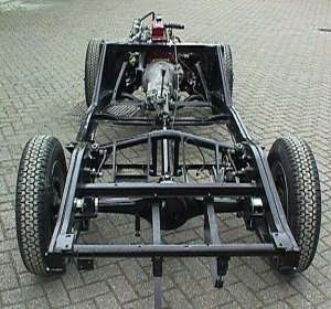
Figure 12 - MGA Rolling Chassis
This frame is very strong since it was designed with an endurance capacity for racing [11]. Also, Bob Wing of Inverness, California, converted a 1959 MGA to electric 25 years ago and the car is still driven and showed today. In a conversation with Mr. Wing in February, he said he has never had a problem with the frame's durability despite the extra 1000 pounds that was added to the original weight of the car. He has towed his MGA all over the country [12]. Our conversion will add less weight than Mr. Wing's did and our weight will be distributed similarly. No further analysis was performed with regards to the strength of the frame.
Other aspects of the MGA's chassis will need modifying and or strengthening before the final product is delivered to the owner. These areas are not included in the scope of this project, but will be addressed eventually. The brake system on the MGA performs poorly
20
by today's standards. The system consists of four-wheel drum brakes. The front can be converted to disk brakes relatively easily with the use of MGA 1600 or MGB brake components. If necessary, the rear brakes can also be converted to a disk brake setup, although a direct swap will be more difficult than with the front end. Suspension pieces such as the shocks and springs (leaf springs in rear) will need to be strengthened for the increased load. Possibilities include using heavy duty springs and shocks from an MGB or increasing the damping force by swapping in heavy duty shock valves [11].
A final weight estimate and weight distribution was calculated for the vehicle after the electrical drivetrain components are installed. Using the weights for each component and their approximate location in the vehicle, the new weight distribution was calculated. A force and moment analysis was used to come up with the final figures. The estimated total weight of the vehicle is 2430 pounds, with 55.2% of the weight distributed to the rear wheels.
The original car weight was 1862 pounds, with 48% on the rear wheels. The lack of room in the engine compartment forced us to locate a majority of the batteries in the rear of the vehicle, causing the weight distribution to shift more toward the rear. With 55.2% of the weight being on the rear wheels, the car will be more stable upon initial acceleration and easier to turn. A spreadsheet with the weight balance data can be found in the Appendix.
Many components will have to be mounted to the frame of the MGA before the completion of the car. Components such as the motor controller, throttle control potentiometer, fuses, high voltage contacter, wires, cables, etc. will have to have mounting hardware designed and fabricated. The motor controller is the larger of these components. It will mount in the space once occupied by the radiator. Two mounting brackets have been designed to mount the controller to the existing engine compartment. They will be made of AISI 1030 12 gauge steel. The drawings of the brackets and the controller with the brackets mounted in the engine compartment can be found in the Appendix.
The project is currently under budget. The cost of motor and controller increased from the time the budget was first estimated. The wiring harness for the motor and controller includes the throttle pot box, which saves the project $85. The drivetrain cost is $371 over what was budgeted.
We increased the number of batteries from the initial estimate for range and acceleration reasons. That, combined with the size restrictions of the car, contributed to the batteries costing $825 over what was budgeted. The batteries have not been ordered yet and we are trying to find a better price. The over budget on the drivetrain and batteries used $1196 of the miscellaneous/contingencey budget, leaving $1443.
The total engineering time to April 30th was 692 hours. At $75 per hour, the total cost for engineering time is $51,919, leaving a surplus of $8,981. Roughly half of the budget has been used in the project. Green Mountain has been on time with their payments. For a summary of the entire budget, see the Appendix.
21
The proposed schedule was planned in order to provide us, the designer, with an efficient amount of time to produce a quality product for our customer. The schedule was set to begin on January 21, and end on August 5, giving us a time period of 24 weeks.
A Gantt chart was developed showing specific tasks along with the starting dates and deadlines for each. The major tasks are broken down further into subsections in this chart, making progress somewhat easier to follow. This chart can be found in the Appendix.
To date, the project is slightly behind schedule. All major tasks and subsections have been started with the exception of the regenerative brake design under chassis research. The major proponent of this delay is the fact that the system manual for our chosen motor system has not yet been received and is necessary to design the regenerative braking system that will be utilized in our conversion kit.
22
Conclusions
The purpose of this project is to design a kit to convert a 1957 MGA 1500 convertible from gas power to electric power. Many different aspects are involved with the conversion: researching and choosing electrical components, removing the fossil fuel powertrain, fabricating hardware to mount the new electric drivetrain, and mounting the new drivetrain. The electrical components include the motor, controller, batteries, battery boxes, wiring, fuses, contactors, and various other devices.
The components chosen for the electric MGA must be reliable, safe, efficient, easy to use, and high quality. The Solectria AC42A alternating current motor will be the powertrain used in the MGA. It will be mounted to the four-speed transmission that is currently in the car. The controller is the also from Solectria. The batteries that will be used are the Hawker Genesis G42EP's. There will be twenty-five of these twelve volt lead-acid batteries in the MGA. No modifications to the car's frame will be made as compensation for the added weight. Some chassis modifications will have to be made, but are not included in the scope of this project. The project is approximately one week behind the intended schedule. Most of this delay is due to the lack of complete specifications for components. The project is under budget currently. Some components such as the motor, controller, and batteries cost more than expected while others like the throttle pot box and materials cost less than expected.
23
References
| [1] |
KTA Services
944 West 21 Street
Upland Ca, 91784
Tel: (909) 949-7914
Fax: (909) 949-7916
www.kta-ev.com
|
| |
| [2] |
Unique Mobility, Inc.
425 Corporate Circle
Golden CO 80401
Tel: (303) 278-2002
Fax: (303) 278-7007
www.uqm.com
|
| |
| [3] |
Solectria Corporation
33 Industrial Way
Wilmington, MA 01887-3433
Tel: (978) 658-2231
Fax: (978) 658-3224
www.solectria.com
|
| |
| [4] | Batteryweb Distributor; http://www.batteryweb.com
|
| |
| [5] | ALABC Consortium; Advanced Lead Acid Battery Consortium, http://www.alabc.org
|
| |
| [6] | Valence Technology; Lithium batteries, http://www.valence.com
|
| |
| [7] | Panasonic; https://na.panasonic.com/us/products-services
|
| |
| [8] | Hawker Energy Products, Inc; Hawker and Genesis batteries, Genesis Selection Guide, Fourth Edition, http://www.hepi.com
|
| |
| [9] | Oberg, E., Jones, F.D., Horton, H.L., and Ryffel, H.H., Machinery's Handbook Twenty-Fifth Edition, Industrial Press Inc., New York, 1996.
|
| |
| [10] | Shigley, J.E. and Mischke, C.R., Mechanical Engineering Design, McGraw-Hill, Inc., New York, 1989.
|
| |
| [11] | MG: The Classic Marque Homepage, www.mgcars.org.uk
|
| |
| [12] | Bob Wing, Media Corespondent/EV Consultant
Inverness, CA
(415) 669-7402
|
24
Bibliography
Concorde; www.concordebattery.com
CSB Battery Technologies, Inc.; http://www.csb-battery.com
DC Battery Specialists; Wholesaler, http://www.dcbattery.com
Douglas & Guardian Battery; http://www.douglasbattery.com
Dynasty Division C&D Technologies, Inc.; http://dynastybattery.com
Electric Fuel, Inc; http://electricfuel.com
Electrosource, Inc; http://www.electrosource.com
Evercel; http://evercel.com
Gel-Tech; https://www.westcobattery.com/marine.htm (broken link)
Lifeline Battery; https://lifelinebatteries.com
Optima; http://www.optimabatteries.com
Power-Sonic; https://www.power-sonic.com
Saft; http://www.saft.fr
Trojan Battery; http://www.trojan-battery.com/intro.html (broken link)
DARPA Consortium; www.calstart.org
USACAR; United States Advanced Battery Consortium, http://www.uscar.org/techno/batterysplrs.htm (broken link)
Moss Motors, Ltd., Sports Car Specialists, www.mossmotors.com
Zweers Restoration and Body Work
Terwolde Nederland
0031 571 281281
contactor
Email: zweers@daxis.nl
North American MGA Register Home Page, www.namgar.com
Barney Gaylord's Homepage, www.mgaguru.com
Email: barneymg@mgaguru.com
25
AC Propulsion
441 Borrego Court
San Dimas, CA 91773
Tel: (909) 592-5399
Fax: (909) 394-4598
www.acpropulsion.com
BRUSA Elektronik
Erlen 116
CH - 9473 Gams
Switzerland
Tel: +41 (0)81 750 35 30
Fax: +41 (0)81 750 35 39
www.rol.ch/BRUSA/fenglish/frame.htm
InnEVations
P.O. Box 2012
Glen Ellen, Ca 95442
Tel: (707) 933-0871
Fax: (707) 933-0872
www.innevations.com
Electric Vehicles of America
P.O. Box 2037
11 Eagle Trace
Wolfeboro, NH 03894
Tel: (603) 569-2100
Fax: (603) 569-2900
www.inc.com/users/evainc.html?999
|
Lynch Motor Company Ltd
P.O. Box 919, Hemingford Road
London N1 1XL, UK
Tel: +44 (0)171 607 8141
Fax: +44 (0)171 609 3625
www.lynchmotor.com
New Generation Motors
www.ngmcorp.com
Electro Automotive
POB 1113-W
Felton, CA 95018-1113
Tel: (831) 429-1989
Fax: (831) 429-1907
www.electroauto.com
Wilde EVolutions, Inc.
PO Box W
Jerome, AZ 86331
Tel: (888) EV-Parts
Fax: (520) 639-0857
www.wilde-evolutions.com
Motion Control Group
Corporate Facility
14700 Martin Drive
Eden Prairie, MN 55344
www.pittman-motors.com
|
26
Appendix
27
|