The MGA With An Attitude
ENGINE OVERHAUL - BE-201C -- Pg 3 of 5
Lower Engine External and Crankshaft Bearings
Things you might skip:
If you ultimately only re-ring the engine without removing it from the car, you will be skipping quite a bit of what is to follow, particularly anything doing with R&R of engine or crankshaft or camshaft.
Section A.16, Removing and Replacing the Timing Cover
You might re-use a cover gasket if it is relatively new and in good condition, but also consider using a bit of liquid sealant. Otherwise figure on always replacing paper gaskets. Very late in MGA production the felt washer seal was replaced by a rubber seal. The late production MGA timing cover with rubber seal uses the same oil thrower ring as the early cover with felt seal. MGB timing covers use the same rubber seal but are different internal shape and use a different oil thrower ring. Many MGA engines have been retro-fit with MGB timing covers. You must use the correct oil thrower ring to match the cover type.
Section A.17, Removing and Replacing the Timing Chain
Fig. A.6 shows the very early production timing chain setup with no chain tensioner. The chain tensioner was added at engine number 259, so most MGA will have the tensioner. See Fig. A.10 in Section A.32 for that information. Fig. A.6 also hows alignment marks on the timing sprockets. Some replacement sprockets may be lacking the alignment marks, so you might need to install the timng sprockets with no marks. When the sprockets are aligned as shown the crankshaft and valve gear are oriented with #1 cylinder at top dead center on the exhaust stroke and #4 cylinder at TDC on compression. This may be confusing later with Ignition timing setup calls for #1 cylinder to be at TDC on compression. To get there you need to rotate the crankshaft one turn, 1/2 turn of the camshaft, which puts the alignment mark 180 degrees away on the opposite side of the cam sprocket.
If your engine has a special performance camshaft the required valve timing may be different. Rather than using an expensive adjustable cam sprocket it is possible to skip the timing chain over one tooth for a 9 degree change of cam timing, and then use an offset cam key to make up a few degrees one way of the other. Bottom line is, for a special camshaft the timing chain alignment procedure may be different.
Section A.18, Removing and Replacing the Power Unit
There are three different propshafts used in the MGA. For early and mid production 1500 cars the gearbox can be removed without disconnecting the propshaft, because the splined front yoke can slide out of the gearbox when pulled apart. For late production 1500 all Twin Cam and late cars the propshaft has bolt flanges on both ends and a sliding spline aft of the front u-joint. It is important to maintain proper alignment of the u-joints in the later propshaft. It is not necessary to mark the flanges on the propshaft. The bolt patterns are offset so the flanges only connect in one of two positions (180 degrees apart), either of which is acceptable for operation. There is otherwise nothing special about orientation of propshaft to gearbox or rear axle.
For any MGA it is possible to R&R the engine without removing the gearbox. If you need to remove the gearbox the engine must come out (but not necessarily together). Some very early production cars had no removable cover on the tunnel, so the tunnel had to be removed to extract the gearbox. For most cars with the separate top cover on the tunnel you can ignore the Book instructions to disassemble the interior of the car for removing the engine and/or gearbox. Also even when you do need to remove the gearbox, I find it easier to remove the engine first and then remove the gearbox separately.
When removing the gearbox, remove the center carpet section from the tunnel, then remove the tunnel top cover. Then remove four bolts to extract the remote shift extension from the gearbox, after which the gearbox can be drawn forward through the engine bay (either attached to engine or engine before gearbox). Removing or reinstalling engine and gearbox together requires high tilt angle and high lift distance, so consider an engine tilt leveler and lots of head room in the workshop. Before removing the gearbox, drain the oil, disconnect speedometer drive cable, and dismount the clutch slave cylinder (2 bolts). The 1500 type propshaft will slide out of the tail of the gearbox, but the 1600 type propshaft needs to be un-bolted from the gearbox.
Section A.19, Removing and Replacing the Sump and Oil Pump Strainer
The Book instructions for cleaning the oil strainer apply to early cars only. In late 1957 the oil pump and strainer were changed. The later style strainer cannot be disassembled. It is also recommended to change the early oil pump and strainer to the later style parts at first opportunity. The early parts have significant restriction to input flow that can cause the oil pump to cavitate at high engine speed (above 6000 rpm), resulting in complete loss of oil flow and possible catastrophic failure of the crankshaft bearings.
Section A.20, Removing and Replacing Main and Big End Bearings
- - Big End Bearings
Be absolutely sure to keep the bearing caps with their original mated con-rods. When originally machined at the factory the bearing cap was cut and fitted to the con-rod first, and the bearing nest was bored afterward. The bore is almost never exactly centered on the split line, so mixing up the bearing caps will always result in some bearings being loose and some bearings seizing up on the crankshaft. It is a good idea to mark the con-rods and bearing caps for mating. If you don't have number stamps, prick punch makes will work as well. Put one punch mark on the end of the bearing cap and a matching punch mark nearby on the con-rod. Ditto for all parts. One punch mark for #1 rod, two punch parks for #2 rod, etc.
- - Main Bearings
Contrary to the Book instructions, it is possible to R&R main bearing shells without removing the crankshaft from the engine. It is also possible to remove the sump and bearing caps with the engine in the car, so you can change bearing shells without removing the engine. If the crankshaft needs to be reground the engine must be removed for disassembly.
The Book has an error in the last paragraph of this section. When refitting thrust washers at the center main bearing the oil grooves must face AWAY FROM the bearing to be in contact with the rotating flanges on the crankshaft.
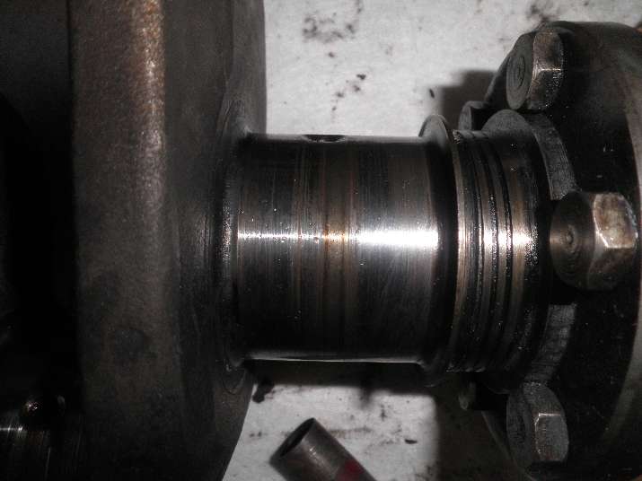
The Book does not say much about determining condition of the crankshaft, only that it should be replaced with a reground one if worn. Run your finger across the ground bearing journal on the crankshaft, front to back. The journals should be mirror clean and perfectly smooth.
 Repeat on top and bottom of the journal. If you can feel even the slightest roughness it needs to be re-ground. If it passes the finger tip test, use a 2 inch micrometer capable of reading .0001" increments to measure the diameter of the bearing journals on the crankshaft. Measure in two or thee different orientations, as the journal may not be round. Refer to the shop manual for correct diameter. If it is more than .001" undersize in any direction it needs to be reground. Regrind sizes will be in increments of 0.010" undersize.
You do not have to buy a new crankshaft. In most cases the old one can be reground (if needed). This is specialty process which is commonly NOT done in a local engine shop. If you can take your crankshaft directly to the grinding shop you might same some money and also be dealing directly with the people doing the work. The shop will inspect the part before machining. They may recommend Magnaflux inspection to check for cracks. This may be a good idea if the part has an unknown history. If this was done in the not too distant past it may not be worth doing again (a judgment call).
A re-ground crankshaft will need matching undersize bearings. If you have it reground the shop will tell you the new sizes for main and rod journals. If you are not having it re-ground, it's a good idea to install new bearings anyway, unless you know for sure the old ones are "like new". Look on the back (OD) of the bearing half shells for size numbers. Standard size may only contain a part number or may be marked "STD". Undersize bearings should be marked with the size, like 010, 020, etc. You must buy new bearings in the correct size to match the crankshaft regrind size.
When installing the crankshaft bearings (mains or rods) be sure everything is absolutely clean. Clean your hands like a operating room surgeon. The only thing allowed on your hands is clean engine oil. The running oil gap is as small as .0005" to .0015" radial clearance, so something as small as a human hair caught behind the bearing shell can make the bearing bind up on crank journal. Try to avoid touching the ID of the bearing. If you do touch it, add a dab of clean oil and wipe it out with your finger tip. If you feel anything at all there, clean it and start again.
Clean the bearing cradle, clean your fingers, put a dab of oil on your finger and run your finger through the bearing cradle. It should be clean and smooth. Your finger tip can feel bits of dirt smaller than .001" (as small as .0001"). If you feel anything there, clean it again. Ditto for the back side of the bearing shell. Wipe off as much oil as you can with your finger, but do not use a rag. You do not need any excess oil film behind the bearing shell.
Install the bearing with the anti-rotation tab positioned in the slot in the cradle. Use a small plastic tool handle to tap on the ends of the bearing shell to seat it fully into the cradle. Rock it back and forth a bit to be sure it is fully seated and flush at the ends. Put main bearing half shells in the block first. Generously oil the bearings and the crank journals. Set the crankshaft into the bearings. Rotate the crank to be sure it turns smoothly and easily.
Install the center journal thrust washers with the white metal side (side with the oil relief slot) facing the rotating surface of the crankshaft. The plain half washers go into the block and can be rotated into place after the crank is in position. The half washers with the anti-rotation tab go on the center main bearing cap before installation, also with the white metal side against the rotating surface of the crank. Oil generously. Tap the center main bearing cap into its seated position. Test rotation of the crank. Install the washers and nuts, torque lightly, and test rotation of the crank. Torque to spec and test rotation of the crank again. If at any time the crankshaft goes tight, disassemble it and start over. You should always be able to turn the crank with your fingers. Repeat for front and rear main bearings. When installing connecting rods later tighten one at a time and check for free rotation of the crankshaft with every step. If anything causes tight rotation of the crankshaft, fix it immediately before you go on.
If you think the crankshaft does not need to be re-ground, you can replace the main bearings while the engine is still in the car. Remove only one bearing cap at a time, so the other two bearings will keep the crankshaft in place. The front main cap is a little tricky, located partially above the suspension cross member, so you need to be a little creative with a bolt and flat washer and pry bar and a block of wood to pull the bearing cap down out of the block. Before removing the front main cap you have to remove the two bottom bolts in the timing cover, as they screw into the bearing cap.
Once a main bearing cap has been removed, the bottom bearing shell should come out with the bearing cap. If the bearing shell sticks to the oil film on the crank journal, you can pull it off with your fingers (or a nudge with a small screwdriver). The top half of the bearing shell can be rotated out of the block in the direction of the anti-rotation tab. Use a small non-metallic wedge to tap on the opposite end of the shell to get it started. Once the tab end of the half shell is exposed you can catch this with your fingers and hold it against the crank journal as you rotate the crankshaft to bring the top shell out 180 degrees to the bottom of the journal where you can pick it off with your fingers.
Installation of the new main bearing top half shell is the reverse of removal. You may need just a little finesse to get it started, as it will have very little running clearance. Apply plenty of oil to the white metal side of the bearing and to the crank journal. Once you have it rotated into place you can install the bottom half shell and the bearing cap. The two anti-rotation tabs go together on the same side of the journal to prevent rotation of the shells in both directions. Don't forget the center bearing thrust washers.
|