The MGA With An Attitude
MGA Crankcase Ventilation, Test and Analysis - CV-101B
Contributed by Bob Shafto
The function of the MGA crankcase ventilation system, is often described as follows;
The open end of the draft tube near the oil pan, is cut at an angle (long side facing up wind) and the air moving under the vehicle flows across the opening while driving, creating a venturi effect, causing a vacuum in the tube. The vacuum draws fresh air into the rocker cover vent from the air filter, down and through engine cavities and crankcase, then out the draft tube. In doing so it removes the harmful blow-by gasses, keeping the crankcase and other internal cavities clean. But does it really?
This article will discuss the physical characteristics, testing and analysis to investigate the actual operation and flow.
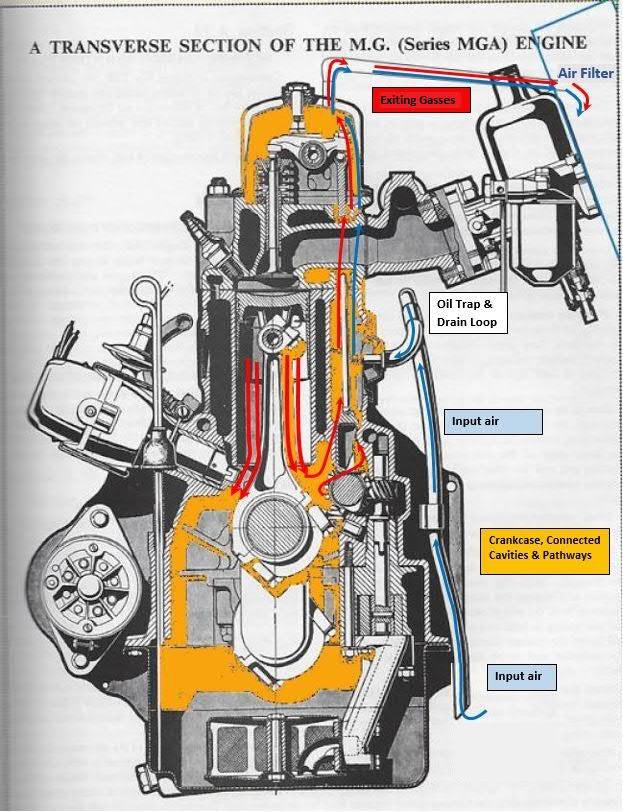
Internal, chamber connections & flow paths:
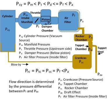
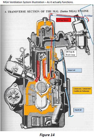
The rocker cover area is connected to the tappet area through the large pushrod holes. These allow both oil drainage and airflow passages. The tappet area also has drain holes connected to the crankcase allowing oil to drain and air to flow.
The combustion chamber typically reaches around 1,200 psi and can reach over 2,000 psi on some engines. This very high pressure, causes combustion gasses (blow-by) to push by the piston rings adding pressure to the crankcase twice every revolution (engine synchronous). The resulting flow and pressure in the crankcase is small but still tends to push oil past seals and gaskets. The blow-by also contains carbons, hydrocarbons and water vapor, all of which can contaminate the oil and harmful to engine internals. On the MGA, the rear of the crank is open to atmosphere so any pressure will push oil out. This pressure needs to be released and gasses vented to prevent pressure buildup and engine damage.
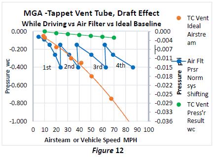
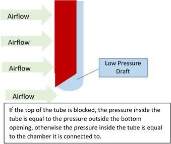 The ventilation system of engines in general, have evolved over time. The first and simple answer is to add a vent somewhere in the system. The blow-by provides the pressure to force flow out the vent but the crankcase is still pressurized and still pushes oil past seals but at a lower pressure. The next step was to extend the vent tube into the air stream beneath the vehicle while driving, creating a draft effect (Figure 2), not a venturi effect (that is entirely different, requiring a narrowing in a civility, flowing air or fluid). The draft effect is a low pressure or small vacuum created behind an object moving through air or fluid. A draft tube usually has an angled opening enhancing the draft effect. The draft tube is an improvement that keeps the crankcase at a slight vacuum while driving and helps keep oil from being pushed out but has no effect when stationary or below about 10 MPH so the crankcase is still pressurized in those conditions. The MG T series connected the rocker cover to the air filter adding vacuum while the engine is running eliminating pressure build up while stationary.
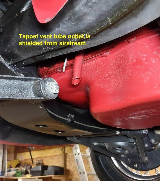
Like the MG T series, the MGA system (figure 1) has two vents, one from the rocker cover (RC vent) into the front air filter but the tappet cover vent (TC vent) was intentionally, reduced in diameter by ½ , moved forward behind the crossmember and
shortened to mid oil pan, 3 above the air stream under the vehicle. This is where the confusion starts. The TC vent tube resembles the draft tube that was on earlier engines so those familiar with draft tubes, assumed this was also a draft tube providing vacuum. Connecting the rocker cover to the air filter must be to draw filtered air through the crankcase to keep it clean from contaminants. The description spreads and repeated over time until it is the accepted theory, without any real examination of the system.
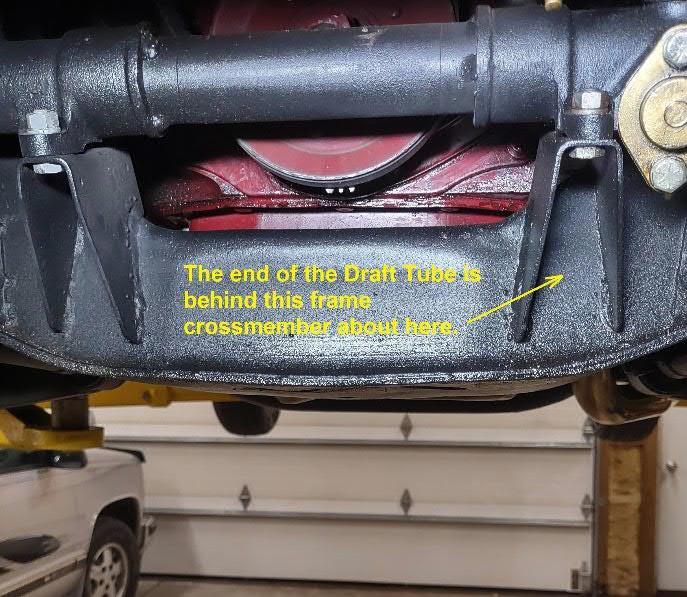
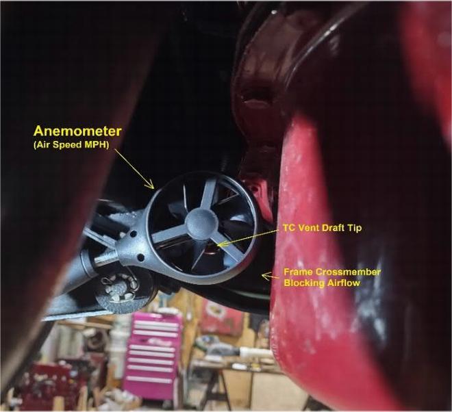
These assumptions are wrong. The placement of the TC vent tube is not in the main air stream flowing under the vehicle but about 3 inches above it and airflow to the tube opening is blocked by the frame crossmember. The cross member acts like a windshield blocking you from wind while you drive. This is critical to how the system actually works. It might look like a draft tube but if it isnt in significant airflow, it cant draft and is not a draft tube, it is a vent.

PRINCIPLES OF AIR & Fluid FLOW
The principals of flow dynamics is attributed to Daniel Bernoulli a Swiss mathematician and physicist in the 1700s. Commonly known as the Bernoulli Principal
The flow of air between two points is due to the occurrence of a pressure difference between the two points. This pressure difference results in a force placed on the air, causing the air to flow from the area of higher pressure to the area of lower pressure.
Crankcase:
Blow-by is the input source, forcing airflow and pressure into the crankcase, tappet cavity, and the rocker area, through connected passages and openings. The higher the rpm the less blow-by per cycle but more cycles per minute and blowby remains nearly constant.
TC vent:
The angle cut, shields the opening from debris and turbulence which could allow puffs of air to oppose the flow of air and under the right conditions and can create a draft effect if gets enough airflow around it. If air flows out of this vent, it will tend to drag oil with it.
The key here - The draft effect is variable with MPH. The tip is not in the main air stream but shielded by and in the draft of the frame crossmember and the front valance. Just like the windshield blocks the wind while youre driving. (Figures
3 & 4)
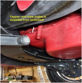
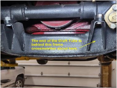
Figure 3Figure 4 Level, Front view
RC vent:
 The RC vent tube is connected inside of the air filter which will always be below atmosphere pressure while the engine is running and the amount of low pressure varies with engine speed or is engine synchronous. The RC vent tube is connected inside of the air filter which will always be below atmosphere pressure while the engine is running and the amount of low pressure varies with engine speed or is engine synchronous.
Air filter chamber:
The air filter chamber is unique to the other chambers in the ventilation system, in that it has both a vacuum source and an atmospheric source as well as being connected to the crankcase. Even though it has its own flow, the pressure of the connected chambers will be additive and equal within the TC vent, crankcase to air filter.
The intake system contains a throttle blade, a damping piston and air filter and all restrict airflow. Each restrictor creates a pressure loss.
The key here: Is that the inside of the air filter will always be below atmosphere (vacuum). It has the least vacuum in the intake system, and is engine synchronous like blow-by. Higher RPM creates more vacuum.
Flow direction (stationary vehicle): A small positive pressure (blow-by) is injected into the crankcase then flows through related chambers toward the vent with the least pressure. When the vehicle is stationary, the TC vent has no draft effect so the system flow is into the air filter. So what happens when the vehicle is moving or air is flowing past the bottom of the TC vent tube? It depends on the draft effect of the TC vent, how fast the vehicle is moving and engine speed.
Now I have questions about the description on page one.
Questions:
1. How much draft can the TC tube actually provide, given that is not in the main air stream under the car?
2. Is the TC tube able to pull fresh air from inside the air filter under normal driving?
3. Can fresh air enter the pressurized crankcase in this system against the air flowing out of the crankcase?
Discussion:
This system is a collection of interconnected chambers and passageways. The area of the openings and passageways are
of sufficient size to allow good flow through the system so pressures will equalize in milliseconds or less. According to physics, pressures measured anywhere inside the system, from crankcase to vent openings will be the same. (Same as house plumbing)
If one vent is strong enough to draw out all the blow-by pressure, the other vent becomes a secondary input.
Crankcase fresh air: (Question 3):
The only way get flow, is to have a pressure differential between the tappet chamber and the crankcase chamber. The flow has to be high pressure to low pressure. Blow-by is being forced into the crankcase chamber, creating pressure and flow continuously. The only way to get flow into the crankcase, is to pressurize the tappet cavity above the pressure of the crankcase. With the RC vent connected to a vacuum and the TC vent in a possible draft, the tappet chamber will always be below atmosphere. Therefore it is impossible to flow fresh air into the crankcase.
Placing a vacuum in the tappet cavity, doesnt increase the possibility of getting air into the crankcase, it decreases it.
Aside from no way to flow fresh air into the crankcase, it is not a necessity for removing blow-by. The water in combustion by products, is actually airborne water vapor that just left the 2800 degrees f combustion chamber and moves out with everything else. When the engine is cold and just started, some water vapor can and does condense on the cold surfaces in the crankcase. As the engine warms up, the condensation evaporates, becoming water vapor again and flows out the vents. Fifteen to twenty minutes of driving and the condensation is gone. The only water vapor left in the crankcase after a 20 min run, is what got there in the last few firings before shutdown. As the engine cools, the vapor can condense on metal parts and that would be the time to evacuate it but no system does. The vapors and contaminants are only an issue if the ventilation is compromised reducing or blocking flow. The only reason for fresh air in the system is to prevent the vacuum from getting strong enough to draw oil out.
The issue is balance between blow-by pressure and vent pressures. At this point, questions 1 & 2 still remain so testing is required to quantify draft effect and system flows.
Test plan:
1. Identify maximum TC tube draft capabilities by placing the tip of the TC vent tube in a controlled and measured air stream. This will quantify the maximum draft effect under ideal conditions, both max and atmosphere.
2. Quantify flow rates and pressure of the two vent tubes by venting both to atmosphere with vehicle stationary.
Identify the pressure produced by blow-by.
3. Identify TC vent capability while driving by measuring airflow directly behind the TC vent tube opening, at 10
mph intervals from 10 MPH to 70 MPH.
4. Measure system pressure while driving at 10 MPH intervals from 10 MPH to 70 MPH.
Testing:
Test 1. Identify the TC vent, draft capabilities.
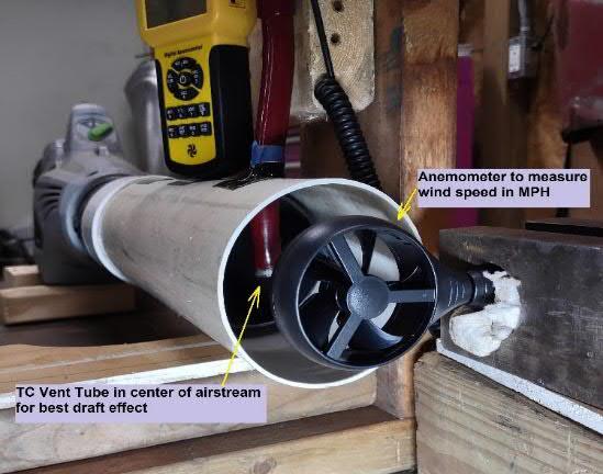
a. Build a wind tunnel to test TC vent tube for maximum draft effect under ideal conditions.
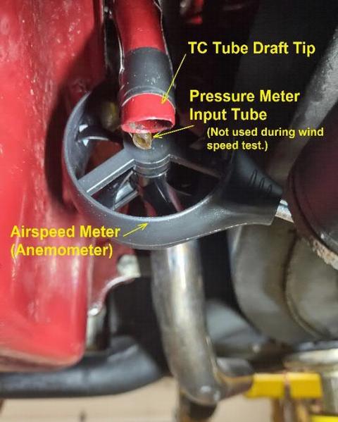
b. Measure the tube pressure generated by draft effect various speeds up to 60 MPH in the center of a 4 dia wind tunnel. This insures the best air stream with nothing blocking the output and no turbulence. The top of the TC tube is open to atmosphere in one test and blocked in another test so no other flows or pressures effect the measurement. Wind provided by variable speed leaf blower attached to 4 diameter tube.
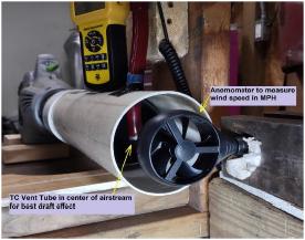
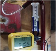
Figure 5Figure 6
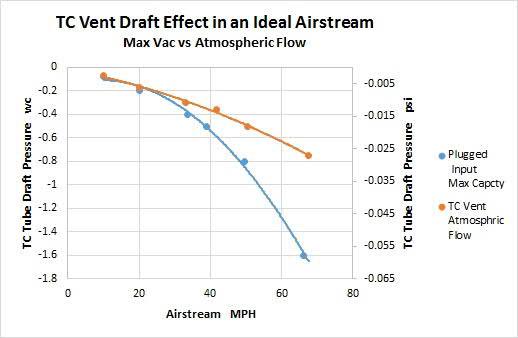
Test 1 Result. Test characterizes both the maximum vacuum and draft effect (no flow) and vented to atmosphere in an ideal air stream. In the vehicle, the tube is not in the main air stream, is blocked by the frame cross member and in turbulent air so the draft effect will be lower in the vehicle than the bench test.
(wc is inches of water column, the vacuum that lifts water 1 through a straw, divide wc by 27.708 to convert to psi)
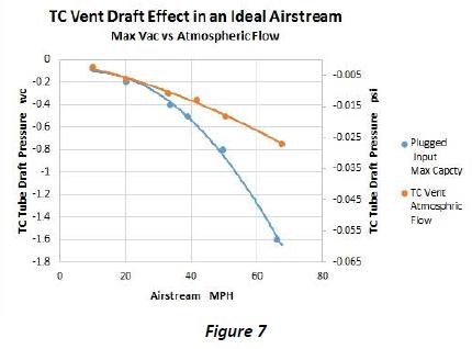
The graph (Figure 7) shows maximum capability of the TC vent tube draft effect, in an unrestricted air stream under ideal conditions. The plugged input data (blue line) shows capabilities of the draft to create vacuum with zero flow through the tube.
The open input (orange) is atmospheric pressure and allows flow through the tube reducing the draft vacuum accordingly.
This is the best the tube can do in ideal conditions.
Test 2. Identify air filter capabilities.
a. Make a cover for the air filter with a hole for pressure tap and install it on the vehicle.
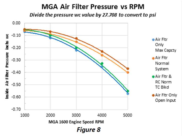
b. Measure air filter chamber pressure at engine speeds from 1000 to 5000 rpm, under three conditions, blocked air filter vent, vent open to atmosphere and normal system connections.
Test 2 Result.
This test shows the maximum vacuum capability (blue) of the air filter with no vent. It also shows the effect when the air filter vent is connected to the RC vent (orange). The pressure rises inside the air filter, as expected due to added system pressure and ambient flow of the TC vent.
Notice that even though the pressures are quite small, the TC vent draft (in an ideal air stream) is capable of more vacuum than the air filter chamber. (Figure 7 vs Figure 8) Humans normally breathe about .30 to .55 wc.
Crankcase max pressure with both vents blocked is 1.8 wc or .065 psi @ 5000 rpm. Limiting factor is probably rear seal. Normal functioning system is < 0.025 wc or 0.009 psi of blow-by.
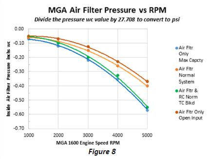
The air filter data reveals even more information about the system when the vehicle is stationary.
The blue line is the air filter without a vent (max capacity). The brown line is the air filter vent open to atmosphere. This is the capability or range of the air filter chamber. When the normal system is connected (orange line), it must fall within the capability range. The normal system (orange line) is near the top of the range, containing blow-by and flow from the tappet chamber vented to atmosphere but also restricted by the 3/8 diameter rocker vent.
If the air filter pressure drops below the blue line, something is adding vacuum to the system (an actual draft tube would cause the pressure to drop below the blue line). Anything above the blue line is adding pressure and flow to the system. Zero on the chart is atmosphere.
When the TC vent is plugged (green line), all the blow-by pressure has to go out the RC vent and the air filter pressure is close to the blue line or max vacuum. The difference between blue line and green line, is the blow-by pressure.
The difference between the plugged TC vent (green line) and open TC vent (orange line) is the air being supplied by the TC vent, preventing excessive vacuum.
Anything between the blue and orange is the capacity for removing blow-by while keeping the system (including crankcase) in a vacuum.
Note: Bad valve seats, guides and seals will allow blow-by into the rocker chamber increasing pressure, decreasing vacuum and input air, from the tappet vent. When the RC vent is connected to the air filter, the air filter chamber becomes part of the entire ventilation system and the pressures equalize throughout the entire system. Which means the air filter chamber is at the same pressure as the crankcase and inside the TC vent tube. Figure 8 proves that the air is drawn into the TC vent from atmosphere when stationary. How does the TC vent influence the system while driving?
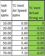
Test 3. Measure the air stream around the TC vent opening, while driving.
a. Install the anemometer 1 behind the TC vent opening in the vehicle, drive the vehicle 0 to 70 mph.
Test 3 Results.
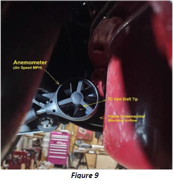
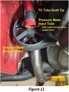
As expected, the positioning of the TC vent opening (Figure 9 & 11) greatly compromises its ability to create a draft effect (green column).
Test 4 result. (Drive test)
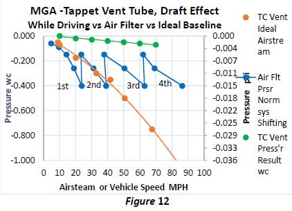 Just like the windshield blocks you from wind while driving, the front valance and crossmember blocks wind from the vent tube. It sees only 10% of the full, main air stream (figure 10) and its max capability (-0.07wc) is barely equal to the minimum air filter vacuum. Perspective; its much less than normal human breathing (0.30 to 0.55wc).
The air filter (blue line) produces more vacuum while driving than the TC vent (green line) at all times.
Due to the positioning of the tube opening, the draft effect cannot overcome the air filer at any speed.
Note: The orange line is what the tappet vent tube is capable of if it were in the main air stream. Overlaid on this chart from previous test data.
Observation: It was observed while driving, that if the clutch were pushed in (coasting) the wind speed measurement reacted to the throttle blips indicating that the engine fan was pushing air into the area behind the frame cross member around the TC vent opening and had more influence than the vehicle speed. Data was only taken with clutch pedal released and steady throttle.
Interesting Note: An Analysis of the Airflow around the MGA Roadster by the Aerophysics Department of the Mississippi State University published in 1963, determined that the high velocity air flowing under the vehicle, creates a low pressure inside the engine compartment. Air flows into the grill down the sides of the engine into the air stream under the car also causes the oval vents to flow into the engine compartment not out of it. Thanks to Nick Kopernik for finding and posting this article https://www.mgexp.com/article/mgb/pdf/mga-roadster-airflow-analysis-msu-1963.pdf
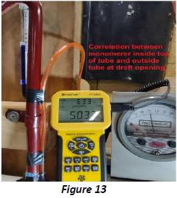
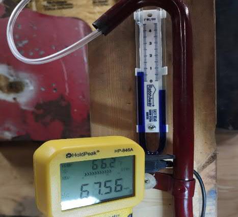
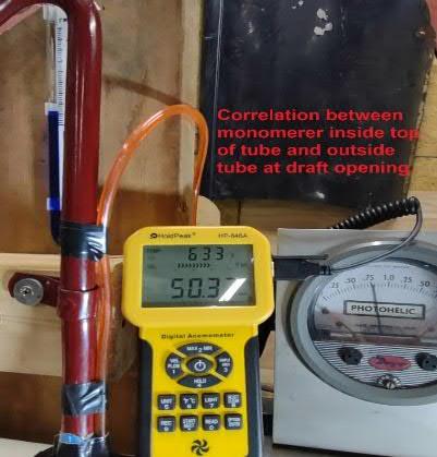
The photo to the left (Figure 13) shows correlation between gauges used in testing and verifies that the placement of the sample tube on the vent tube is correctly positioned for accurate, in vehicle use. The manometer tube gauge on the left matches the Dwyer gauge on the right and the air speed in the center is 50 mph.
A final road test tracked the previous test data but there was an issue with the differential meters I am using. One input is for sensing the other is for atmospheric pressure. The Roadster cockpit has a big draft effect of its own and creates a lower pressure than ventilation system, making the ventilation positive in respect. Placing the atmosphere input between the heater box and firewall, did keep the meter readings negative and they did track the earlier test data but had an off set due to the engine bay not truly at atmospheric pressure. The TC vent and air filter did have identical readings, confirming that the entire system was at the same pressure and controlled by the air filter.
Conclusion: A well maintained and properly working engine and MGA crankcase ventilation system, always draws blow-by gasses into the air filter, is synchronous to engine speed and blow-by, draws fresh air up through the TC vent but does not flow fresh air into the crankcase and the TC vent has no meaningful draft effect.
 Summary: The blow-by and vent pressures are small. The stock system always flows into the air filter, consuming all blow-by as it is created. This is a very effective system and very close to the later PCV system.
The key is to have just enough vacuum to draw all the blow-by gasses and create a small negative pressure to prevent oil leakage through seals and gaskets but not enough vacuum to draw oil through the vents.
Advantage: System always has a small vacuum, protects against oil exiting the TC vent, engine seals, recycles all blow-by gasses and is always functioning when blow-by is being generated (engine and blow-by synchronous).
Disadvantage: The vacuum is small but may draw a very small amount of road dust (not grains of sand or dirt) into the tappet chamber. Dust is likely to get trapped in oil and drained into the sump and what doesnt sink will get pumped through the oil filter before oiling the system. A 15mm breather filter from ADD-W1 is a good solution.
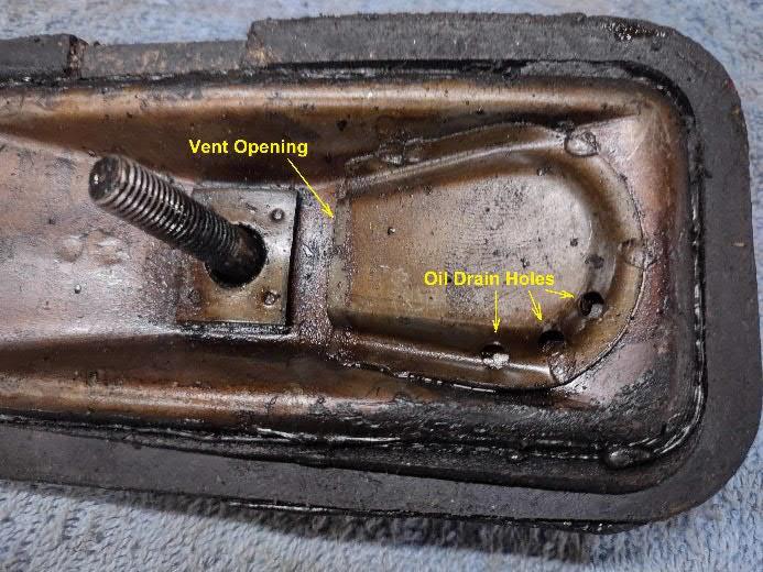
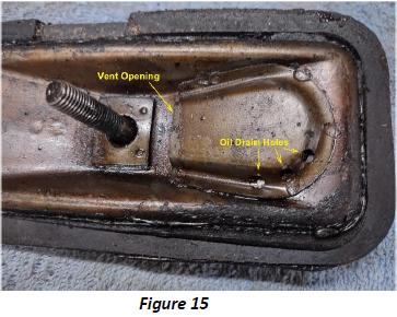
Diagnostics: If you have oil in the air filter chamber, it is an indication that you have too much vacuum in the system. This could mean the air filter is dirty or an issue with the tappet cover vent. Inspect and clean the vent tube and clean the tappet cover and dust trap. (Figure 15) Clean or replace the air filter.
If you have oil dripping from the TC vent tube, there is likely not enough vacuum in the system so inspect and clean the RC vent tube, air filter leaks, holes or damage and that the air filter isnt blocking the vent. Bad rings, valve seats, guides and seals will also reduce vacuum.
 Opinion:
The system works as the engineers intended and they got it right. I really don't think it was an oversight or mistake on their part. On the MGA, the tappet vent is intentionally, ½ the diameter of the T series, shortened to 3 above the air stream and moved forward behind the front crossmember that blocks the airflow. It resembles a draft tube but that doesn't mean it is, or was supposed to be. In this application it does not function as a draft tube and should not be referred to as a draft tube. Its misleading.
-- Bob Shafto
|