The MGA With An Attitude
MGA Front FRAME EXTENSION Modification - FR-101B
AHH5129 for MGA 1500 Fin.(c)66573 without sway bar
AHH5129 for MGA Twin Cam Fin.(c)2274 without sway bar
AHH5924 for MGA Twin Cam Com.(c)2275 with sway bar
AHH5924 for MGA 1500 Com.(c)66574 with sway bar
AHH5924 for MGA 1600 Com.(c)68851 with sway bar
|
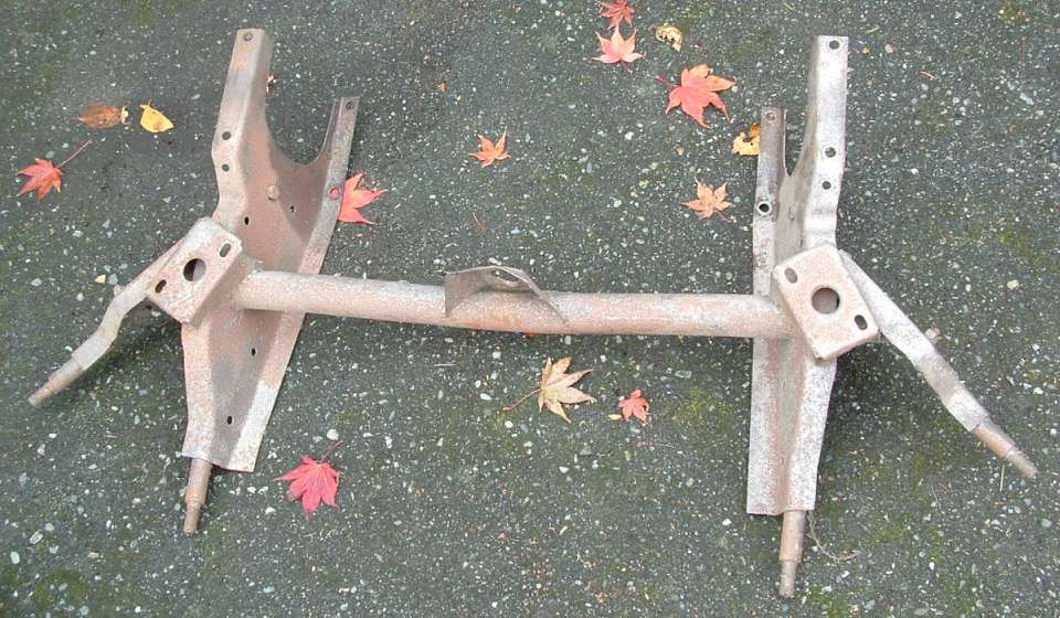
In April 1959, at Chassis No: 66574, the MGA frame front extension and spring pan assemblies were changed to accept installation of an anti-roll bar. Adding a sway bar is a popular suspension upgrade. This article offers a method to modify the earlier frame extension to meet later specification to allow installation of an original type sway bar on top.
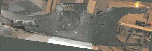
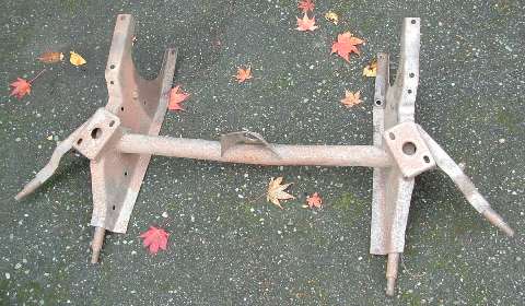
The objective here is to make the early frame (above) look like the later frame (below).
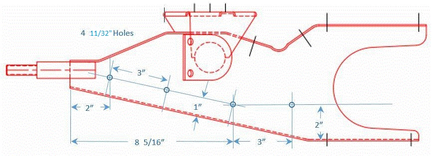
Click on image above for a printable template. Print this on 8-1/2" x 11" paper with 1/4 inch margins (in landscape mode) to produce a full scale template. Cut out the template, position it under the top flange and flush with rear of frame, and mark along the top contour for a cutting line. Also make a horizontal line 1/4 inch below the flange. Cut out the resulting pattern as shown below.
Bend up the 1/4 inch flange and flatten it into the same plane with the wide top flange as shown above. Then make a saw cut through the top flange as shown below.
Bend the top flange pieces downward and form them to match the contour of the cut edge underneath, then sitting on top of the side plate. Intended offset of the radius below the inclined flanges is 0.075" (1x thickness of the sheet metal). Add a short strip of 14-gauge (.075" thick) steel to fill the space between the flange ends. Weld the new piece in place with continuous butt welds and grind smooth. Cut back the inboard edge of the flange to match the sloping side. Form it slightly to produce a matching fillet curve (optional for appearance). Weld the flange to the side slope with continuous weld and grind smooth. When finished the top flanges should be horizontal as compared with a straight edge laid across the flanges from one side to the other.
This configuration is like the original late model factory part, allowing for use of a 5/8-inch sway bar and 1/8-inch wall thickness mounting bushing. If you intend to use a larger sway bar, you could form the part with the depression slightly lower (so not to interfere with the body inner fender).
NOTE 1: Refer to the image above. It will be best if you have your sway bar mounting bushings and brackets in hand before this next step. Original type bushings have flanged ends. You may need to trim the frame flange narrower in the bushing mounting area to fit between the end flanges on the bushing.
NOTE 2: Next, you will drill two 11/32" dia holes each side to accept 5/16" bolts. These holes should be located as near as possible midway across the frame flange, so the bracket and bushing will be properly aligned. Width of your frame may vary from the norm or average in this area. I presume that these holes were punched in the metal before forming of the original parts, as the holes vary somewhat in location from one part to another. Variation up to 1/4" left or right has no significant affect on function of the sway bar, but the holes should be in line front to back to maintain proper alignment of the bushing.
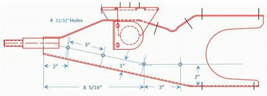
Addendum June 9, 2023:
This additional drawing, provided by Bob Shafto, shows locations of holes for horn mounting brackets. The two holes on horizontal alignment 2-inches from bottom were original issue for MGA 1500 cars. When the top notch was added for sway bar mount, two more holes were added each side for horn mounting in more forward position. Those are the holes at angle 1-inch from bottom near the front of the frame. The 1500 type frame would have only the first two holes each side. The 1600 type frame would have all four holes each side. Adding the two forward holes can be part of the conversion process to modify the 1500 frame to 1600 specification.
|