The MGA With An Attitude
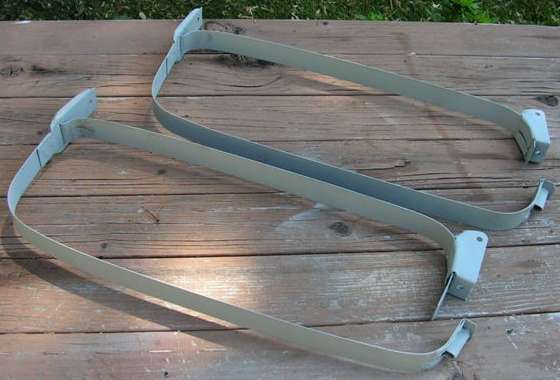
Jack Wannenwetsch near Rochester, New York, USA made his own fuel tank hanger straps.

 After many email messages and several trips under my car for inspection and measurements, I managed to turn this into formal CAD drawings. Click images below to download a 9-page 1.8-MB pdf file with full scale printable drawings. Some additional notes on fabrication will follow below.    Pages 1 and 2 of the PDF file show the fuel tank installation in the car. Fasteners for installation are clearly listed in the Service Parts List, but I will post it here anyway.
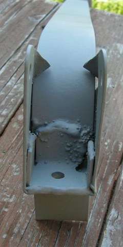
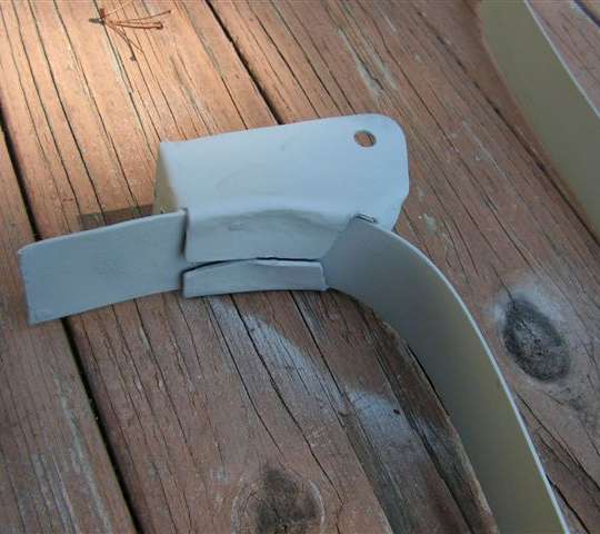
Page 3 shows alignment and welding of the small parts onto the long formed strap. For a concours show car the assembly should be spot welded. For a functional daily driver car, plug welds work as well. Page 4 details forming of the thin steel strap just in case you were inclined to be that precise. Inside bend radius is intended to be 1/2 thickness of the metal unless otherwise specified. Minimally it requires a little curvature near the ends to fit the top and bottom hanger parts. It also requires the offset "S" bend about half way around where it steps through the slot in the front hanger. That offset is essentially 2 times thickness of the metal. Otherwise if you leave the rest of the strap flat, then wrap it around the tank (with the rubber packing in place) and install the clamp bolt, the strap will most likely conform to shape of the tank well enough to server the purpose. The only "trick" is to position the clamps and hangers to give the tank the desired "angle of dangle" as shown on page 2. If the tank position is wrong the filler pipe may have interference with the boot floor. Pages 5, 6, and 7 show fabrication of the upper rear hanger. 5 is the outer shell. 6 is a wood block that may be used for hammer forming the outer shell. 7 is a small part that fits inside of the outer shell to sandwich the strap in between. Page 8 shows the lower rear clamping bracket. This can be formed by wrapping the sheet around a 9/32" diameter steel rod, tapping it down between vice jaws, and giving it a final pinch in the vice. Then hammer form the two flanges flat over the vice jaws. Finish by bending the tails in the vice. Page 9 shows the front bracket. This piece originally has an offset flange around the sides that may be somewhat difficult to form by hand. The offset is 1/4 inch deep at the top end, but less than 1/8 inch deep lower down. It would be good if you can try diligently to replicate this form, as it is a stiffening rib that should help solidify position of the tank in the chassis. The tank assembly full of fuel will weight close to 100 pounds (nominally 25 pounds on each bracket plus the stress of severe shaking of the tank when driving on a rough road). A flat bracket might flex too much leading to stress cracks and possible bracket failure (although I have never heard of an original one breaking in service). All of the drawings were made full scale. When printed full size on the appropriate size paper the layout in the flat views can be used as a tracing template for cutting the bracket pieces out of sheet metal. For final finish clean and paint the welded straps in Satin Black (or whatever other odd color you may have used to paint the chassis parts). |