The MGA With An Attitude
Body Sill Replacement - RT-632
Body Installation
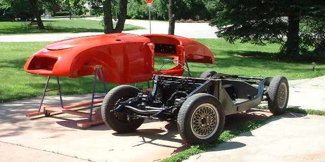
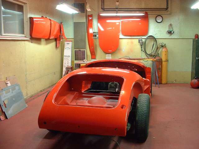
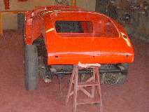
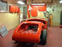
The estranged couple getting back together after six months of therapy.
By mid afternoon I had pushed things around a bit to get the rolling chassis back in the work shop along with the body. I spent an hour or so running various size taps through all of the female threads on the body and frame to clean out any paint and dirt (mostly using a variable speed reversible power drill). I also installed about twenty 3/8" plastic flush plugs in holes in the outboard walls of the frame that I had drilled 30 years earlier for application of Waxoil inside (the plugs had been removed for painting the fame).
The final chore before "lift-on" was to touch up some of the cork packing (1/8" thick) on top of the frame goal post and other smaller pads on the frame where the body mates up. Then I ran 1/4-inch thick x 3/4-inch wide closed cell foam rubber adhesive seal strip for five feet down each side of the frame from the goal post to rear plywood bulkhead (and a couple inches farther). All ready now to set the body on first thing tomorrow.

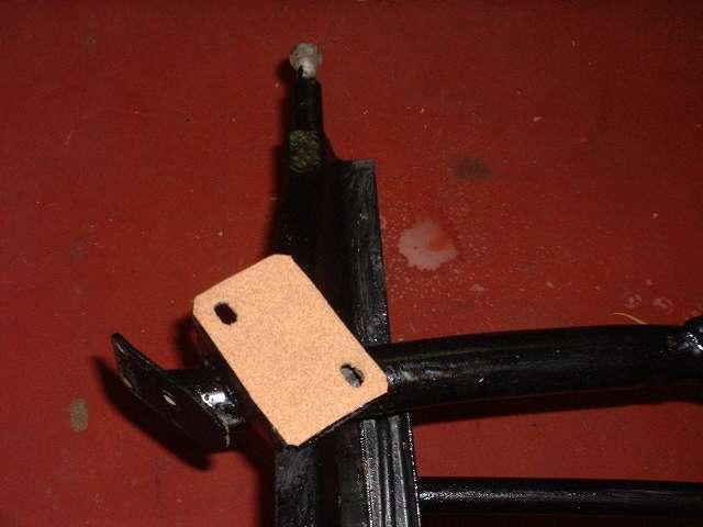
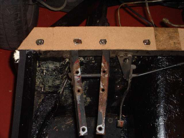
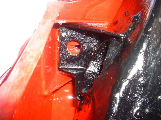
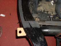
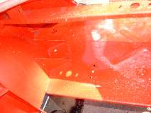
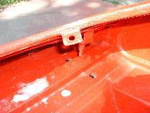
Cork pads on front frame extension (4 bolts), top of goal post (9 bolts), ahead of the A-post (2 bolts), aft of the B-post (2 bolts), aft of the rear axle (2 bolts), and at rear corners (4 bolts). There are also vertical cork strips on the sizes of the goalpost, to be glued to the front flange of the frame closure plate (4 bolts each side, not pictured). Total 31 bolts. Notice in center photo above there is a touch of white at the left side. This is (coincidentally) at the top of the frame side cover plate. The wide body flange sitting on the rubber seal stops a wee bit short of the goal post at this point. It is a good idea to close this small gap with caulking (which can be applied from inside after the body is installed).
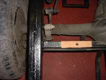
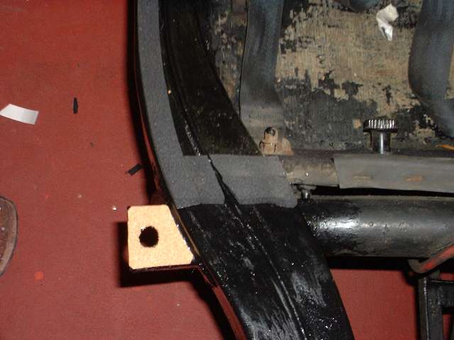
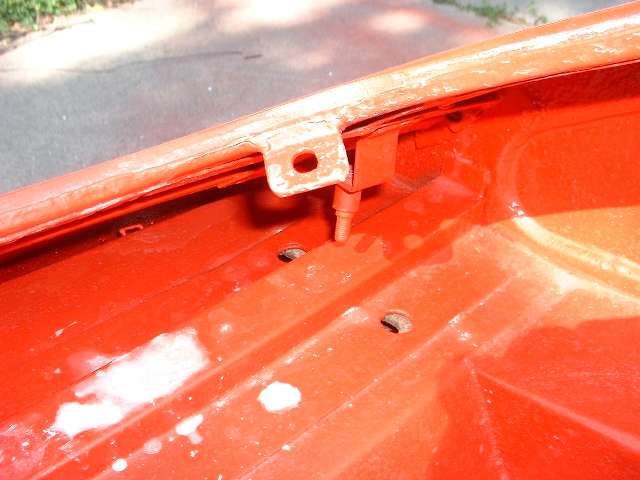
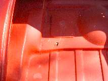
Notice the foam rubber seal running the length of the cockpit along the side rail. At the rear plywood bulkhead there is additional rubber seal installed across the frame side rail. It will also get some caulking on top of the rubber seal at this point. This is much easier to caulk while the body is still loose and can be lifted slightly for access, then set the body down on the caulking. The point of interest here is the front of the rear body shelf, actually the front edges of the trunk floor assembly, at either side of the battery cover opening. I had to learn the hard way that if this point is not sealed, when you drive in heavy rain copious amounts of water thrown up by the rear tires can run down the frame here to soak the cockpit carpeting. This is a real bear for access from behind and underneath after the car is completely assembled. I did this once by putting a short piece of plastic tubing over the nozzle end of a caulking gun. .... (17 June 08)
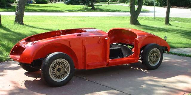
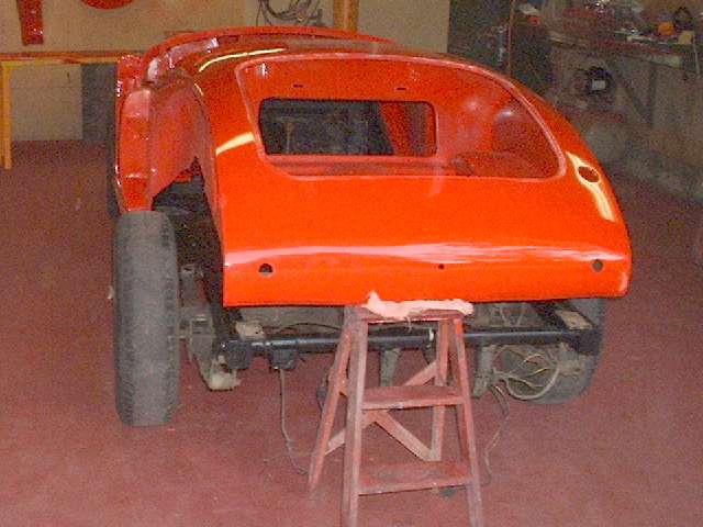
Ah, it feels so good to be one again.
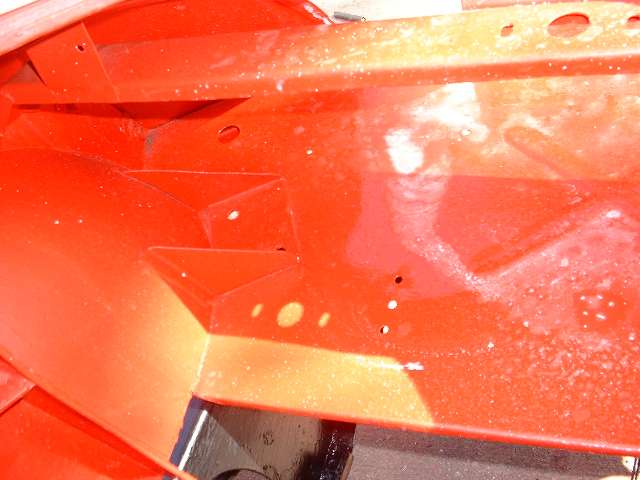
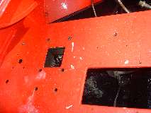
The following six photos show body mounting points correspond to the same six locations on the frame shown above. Front frame extension (4 bolts), top of goal post (9 bolts), ahead of the A-post (2 bolts), aft of the B-post (2 bolts), aft of the rear axle (2 bolts), and at rear corners (4 bolts), total 23 bolts.
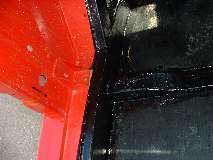
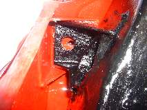
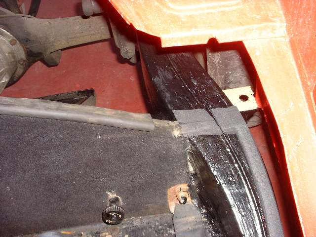
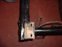
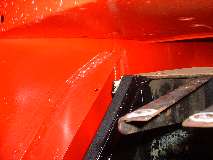
 Before installing the bolts I lift the body at the rear to have access to the seal points at the front and rear corners of the cockpit. Three photos immediately below show the cockpit rear corner seal area before caulking, after set down, and after bolting tight and cleanup. The caulking bead here was very large, at least 3/8-inch diameter, starting from the end of the battery cover seal on the top edge of the plywood bulkhead, and running right across the full width of the foam rubber to the outboard side of the frame. This joint will be mostly hidden under the side rail carpet.

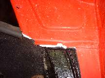
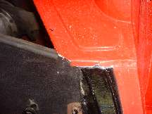
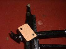
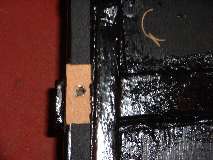
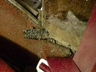 Photo at far right shows the original packing piece in this joint. It is impossible to determine the cross section of this piece with 55 year old decomposed rubber. Image immediate right is from the Service Parts List,
 showing a thick rubber seal with a slot that will accept the front lip of the body fixed battery cover panel.
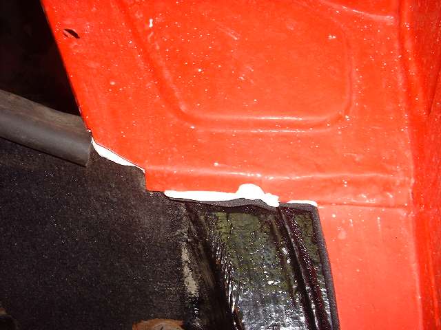
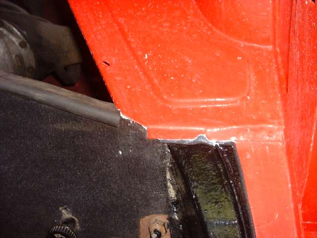
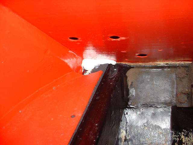
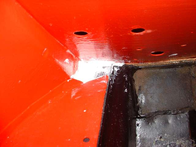
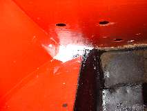
Photos below show the cockpit front corner seal area where the body flange stops short of the heater shelf before caulking, after caulking and set down, and after bolting tight and additional finish caulking. When the caulking dries I will probably hit it with a touch of red paint to reduce the visual impact, in case anyone might ever look under the dash.

 An hour later 18 bolts had been installed and tightened all around the perimeter of the body to frame, leaving out 7 in the center of the heater shelf for now. The body is down tight, hopefully not to budge again for decades to come. The final step was four bolts in a vertical row on each side to "tighten" the body onto the goalpost. Today the paint booth has officially been converted back to a workshop. The temporary body dolly has been disassembled, saving the wheels, screws and lumber. I think I will install the outer body panels before bringing back the shelving, tool cabinet, tires, and all the little bits I like to have handy hanging on the pegboard. .... (19 June 08)
|